
Applied Statics and Strength of Materials (6th Edition)
6th Edition
ISBN: 9780133840544
Author: George F. Limbrunner, Craig D'Allaird, Leonard Spiegel
Publisher: PEARSON
expand_more
expand_more
format_list_bulleted
Concept explainers
Videos
Textbook Question
thumb_up100%
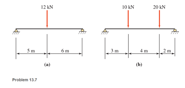
Chapter 13, Problem 13.7P
Calculate the shear and bending moment at 4 m and 7 m from the left end of the beams shown. Show free-body diagrams.
Expert Solution & Answer

Learn your wayIncludes step-by-step video

schedule04:56
Students have asked these similar questions
Draw the Shear force and bending moment diagram
for the beam as shown in figure.
Construct the bending Moment (M) and Shearing force diagram for the beam. (Very detailed explanation by method of section)
For the beam shown below:
Calculate the reactions and fixing moment at the wall.
Draw the shear force and bending moment diagrams.
Determine the maximum shear force and bending moment values.
9 kN
6 kN
9 kN
1 m, 1 m
*
2 m
5 kN/m
2 m
1 m 1 m
*
Chapter 13 Solutions
Applied Statics and Strength of Materials (6th Edition)
Ch. 13 - through 13.6 Calculate the reactions at points A...Ch. 13 - Calculate the reactions at points A and B for the...Ch. 13 - through 13.6 Calculate the reactions at points A...Ch. 13 - Calculate the reactions at points A and B for the...Ch. 13 - Calculate the reactions at points A and B for the...Ch. 13 - Calculate the reactions at points A and B for the...Ch. 13 - Calculate the shear and bending moment at 4 m and...Ch. 13 - Calculate the shear and bending moment at 3 ft and...Ch. 13 - Calculate the shear and bending moment at midspan...Ch. 13 - Calculate the shear and bending moment at 5 ft and...
Ch. 13 - Calculate the shear and bending moment at 5 m and...Ch. 13 - For the beams shown, draw complete shear diagrams.Ch. 13 - For the beams shown, draw complete shear diagrams.Ch. 13 - Prob. 13.14PCh. 13 - For the beams shown, draw complete shear diagrams.Ch. 13 - For the beams shown (next page), draw complete...Ch. 13 - For the beams shown (next page), draw complete...Ch. 13 - For the beams shown (next page), draw complete...Ch. 13 - For the beams shown (next page), draw complete...Ch. 13 - For the beams shown (next page), draw complete...Ch. 13 - For the beams shown, draw complete shear and...Ch. 13 - For the beams shown, draw complete shear and...Ch. 13 - For the beams shown, draw complete shear and...Ch. 13 - A moving-load system is composed of two...Ch. 13 - A moving-load system is composed of two...Ch. 13 - One of the standard truck loads used in the design...Ch. 13 - Write a computer program that will calculate the...Ch. 13 - Write a program that will calculate the shear and...Ch. 13 - Viking Consultants wishes to generate a table of...Ch. 13 - Calculate the reactions for the simple beams...Ch. 13 - Calculate the reactions for the overhanging beams...Ch. 13 - Calculate the reactions at points A and B for the...Ch. 13 - Calculate the reactions at points A and B for the...Ch. 13 - For the beams of Problem 13.33, calculate the...Ch. 13 - For the beam shown, calculate the shear and...Ch. 13 - Calculate the shear and bending moment at points 4...Ch. 13 - Calculate the shear arid bending moment at points...Ch. 13 - Calculate the shear and bending moment at points...Ch. 13 - Refer to the beam shown and draw complete shear...Ch. 13 - Refer to the beam shown and draw complete shear...Ch. 13 - Refer to the beam shown and draw complete shear...Ch. 13 - Refer to the beam shown and draw complete shear...Ch. 13 - Refer to the beam shown and draw complete shear...Ch. 13 - Refer to the beam shown and draw complete shear...Ch. 13 - Refer to the beam shown and draw complete shear...Ch. 13 - Refer to the beam shown and draw complete shear...Ch. 13 - Refer to the beam shown and draw complete shear...Ch. 13 - Refer to the indicated problem and draw complete...Ch. 13 - Refer to the indicated problem and draw complete...Ch. 13 - Refer to the indicated problem and draw complete...Ch. 13 - Refer to the indicated problem and draw complete...Ch. 13 - Refer to the indicated problem and draw complete...Ch. 13 - Refer to the indicated problem and draw complete...Ch. 13 - Refer to the indicated problem and draw complete...Ch. 13 - Refer to the indicated problem and draw complete...Ch. 13 - Refer to the indicated problem and draw complete...Ch. 13 - Refer to the indicated problem and draw complete...Ch. 13 - Refer to the indicated problem and draw complete...Ch. 13 - A two-axle roller with axles 5 m apart passes over...Ch. 13 - A moving load system with wheels at fixed...Ch. 13 - A moving-load system with wheels spaced as shown...
Additional Engineering Textbook Solutions
Find more solutions based on key concepts
1.1 What is the difference between an atom and a molecule? A molecule and a crystal?
Manufacturing Engineering & Technology
The copper shaft is subjected to the axial loads shown. Determine the displacement of end A with respect to end...
Mechanics of Materials
What parts are included in the vehicle chassis?
Automotive Technology: Principles, Diagnosis, And Service (6th Edition) (halderman Automotive Series)
What parts are included in the vehicle chassis?
Automotive Technology: Principles, Diagnosis, and Service (5th Edition)
In each case, construct the parallelogram law to show FR = F1 + F2. Then establish the triangle rule, where FR ...
Statics and Mechanics of Materials (5th Edition)
The zero force members in the truss.
Engineering Mechanics: Statics & Dynamics (14th Edition)
Knowledge Booster


Learn more about
Need a deep-dive on the concept behind this application? Look no further. Learn more about this topic, mechanical-engineering and related others by exploring similar questions and additional content below.Similar questions
- (a) derive equations for the shear force V and the bending moment M for any location in the beam. Place the origin at point A.) (b) use the derived functions to plot the shear-force and bending-moment diagrams for the beam. Specify the values for key points on the diagrams. Wo A Larrow_forwardDraw the shear force and bending moment diagrams of the beam given in the figure.arrow_forwardFor the beam shown, the magnitude of the distributed load is wo = 11.8 kN/m and the beam length is L = 7.9 m. (a) derive equations for the shear force Vand the bending moment M for any location in the beam. Place the origin at point A. (b) use the derived functions to plot the shear-force and bending-moment diagrams for the beam. Use your diagrams to determine the maximum shear force and maximum bending moment. Note that answers may be positive or negative. Here, "maximum" refers to the largest magnitude value, but you should enter your shear force and bending moment with the correct sign, using the sign convention presented in Section 7.2 of the textbook. If the magnitudes of the largest positive and largest negative values are the same, enter a positive number. Wo A В L. Answer: Vmax = kN Mmax kN•marrow_forward
- For the beam shown, the magnitude of the distributed load is Wo = 10.4 kN/m and the beam length is L = 4.8 m. (a) derive equations for the shear force Vand the bending moment M for any location in the beam. Place the origin at point A. (b) use the derived functions to plot the shear-force and bending-moment diagrams for the beam. Use your diagrams to determine the maximum shear force and maximum bending moment. Note that answers may be positive or negative. Here, "maximum" refers to the largest magnitude value, but you should enter your shear force and bending moment with the correct sign, using the sign convention presented in Section 7.2 of the textbook. If the magnitudes of the largest positive and largest negative values are the same, enter a positive number. Wo A L Answer: Vmax = kN Mmax = kN•m Save for Later Attempts: 0 of 1 used Submit Answerarrow_forwardFor the beam shown below, provide equations at each section. Draw the shear and moment diagram of the beam on the space provided below.arrow_forwardCalculate the shear force and bending moment for the simply supported beam of length 8m with the self-weight of 1OKN given below. Also draw the shear force and bending moment diagrams. 6 kN 5 kN 4 kN 1m 2m 3marrow_forward
- For the beam shown on the picture select the corresponding shear force and bending moment diagrams from belowarrow_forwardDraw the shear and bending moment diagram for the following beam and indicate the values of the maximum shear and maximum moment. Need free body diagramsarrow_forwardWhat is the maximum intensity of moment for the beam loaded as shown? What is the degree of curve on the moment diagram at segment CD? What is the value of x, the additional point of zero shear from C?arrow_forward
- find the bending moment diagram for this beamarrow_forward2. For the 20 meter beam shown, there is a roller at "A" (Ay = 52 kN; it is acting upward), and a pin joint at "B" (By=-- 17 kN; it is acting downward). (a) Draw complete shear force and bending moment diagrams. (b) If x=0 is at the left end of the beam, write equations for the shear force and bending moment, and indicate the appropriate sections. (You may use the table on the next page.) 50 KN 15 KN A 90 kN-m 2 m3 m -5 m B *4 -7 m 120 kN-m € 3 marrow_forwardWhen loads and moments are applied to the cantilever beam as shown in the picture below, draw the shear and bending moment lines.arrow_forward
arrow_back_ios
SEE MORE QUESTIONS
arrow_forward_ios
Recommended textbooks for you
 Elements Of ElectromagneticsMechanical EngineeringISBN:9780190698614Author:Sadiku, Matthew N. O.Publisher:Oxford University Press
 Mechanics of Materials (10th Edition)Mechanical EngineeringISBN:9780134319650Author:Russell C. HibbelerPublisher:PEARSON
 Thermodynamics: An Engineering ApproachMechanical EngineeringISBN:9781259822674Author:Yunus A. Cengel Dr., Michael A. BolesPublisher:McGraw-Hill Education
 Control Systems EngineeringMechanical EngineeringISBN:9781118170519Author:Norman S. NisePublisher:WILEY
 Mechanics of Materials (MindTap Course List)Mechanical EngineeringISBN:9781337093347Author:Barry J. Goodno, James M. GerePublisher:Cengage Learning
 Engineering Mechanics: StaticsMechanical EngineeringISBN:9781118807330Author:James L. Meriam, L. G. Kraige, J. N. BoltonPublisher:WILEY
Elements Of Electromagnetics
Mechanical Engineering
ISBN:9780190698614
Author:Sadiku, Matthew N. O.
Publisher:Oxford University Press
Mechanics of Materials (10th Edition)
Mechanical Engineering
ISBN:9780134319650
Author:Russell C. Hibbeler
Publisher:PEARSON
Thermodynamics: An Engineering Approach
Mechanical Engineering
ISBN:9781259822674
Author:Yunus A. Cengel Dr., Michael A. Boles
Publisher:McGraw-Hill Education
Control Systems Engineering
Mechanical Engineering
ISBN:9781118170519
Author:Norman S. Nise
Publisher:WILEY
Mechanics of Materials (MindTap Course List)
Mechanical Engineering
ISBN:9781337093347
Author:Barry J. Goodno, James M. Gere
Publisher:Cengage Learning
Engineering Mechanics: Statics
Mechanical Engineering
ISBN:9781118807330
Author:James L. Meriam, L. G. Kraige, J. N. Bolton
Publisher:WILEY
Understanding Shear Force and Bending Moment Diagrams; Author: The Efficient Engineer;https://www.youtube.com/watch?v=C-FEVzI8oe8;License: Standard YouTube License, CC-BY
Bending Stress; Author: moodlemech;https://www.youtube.com/watch?v=9QIqewkE6xM;License: Standard Youtube License