
Concept explainers
The resultant load on the most stressed bolt using eccentricity method.
Answer to Problem 13.1PFS
17.39k
Explanation of Solution
Given:
The given connection is,
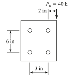
Calculation:
Calculate factored load for LRFD.
Calculate factored load for ASD.
The gross yielding area is calculated as,
The number of bolts required by using LRFD can be calculated as follows.
Where,
We can calculate the
So, we can calculate the bearing strength of the bolt using the formula,
Substitute the all value in the above formula and we get that,
Substitute these values in the design strength formula then we get that,
Now, calculate the number of bolts required for the connection using LRFD by the formula,
Conclusion:
Hence, the resultant force of the bolt is 17.39k.
Want to see more full solutions like this?
Chapter 13 Solutions
Structural Steel Design (6th Edition)


- The truss member shown in the accompanying illustration consists of two C12 x 25s(A36 steel) connected to a 25 mm gusset plate. How many 22 mm A325 bolts (threads excludedfrom shear plane) are required to develop the full design tensile capacity of the member if it isused as a bearing-type connection? Assume U = 0.85. Use ASD method.arrow_forward2-PL10x1/2 A-36 Bolts are 7/8 in A-325, threads are not excluded. All edge spacings are minimum | 3" | 3" | о PL 10x3/4 A-572Gr50 a) Determine the nominal bolt capacity. b) Determine the nominal bearing capacity for each plate. c) Determine the nominal rupture capacity of each plate. d) What is the nominal capacity of the connection? e) Using LRFD, is this connection capable of supporting a dead load of 150 kip and a live load of 100 kip?arrow_forward6. Investigate the tension member connection as shown in Figure below to carry a total service load of 75 kips. The connection is a bearing type connection with threads exclude (from shear planes, using 7/8 in diam. A325 bolts in standard holes). The plates are A572 Grade 50 steel. Use the AISC Specification. O O O Plates 5 Assume standard size holes X6 Tarrow_forward
- The diameter of the holes in the connection below is 20mm. The steel plate is made up of 10mm x 250mm with staggered bolts. Use A36 steel and LRFD approach. 50 50 T- 30 B 250mm D. 50 E. 50 60 75 Determine the design tensile strength of the connection (neglect block shear) in kN.arrow_forwardThe bracket connection shown in Figure must support an eccentric load consisting of 9 kips of dead load and 27 kips of live load. The connection was designed to have two vertical rows of four bolts, but one bolt was inadvertently omitted. If 7⁄8inchdiameter Group A bearingtype bolts are used, is the connection adequate? Assume that the bolt threads are in the plane of shear. Use A36 steel for the bracket, A992 steel for the W6 x 25, and perform the following analyses: (a) elastic analysis, (b) ultimate strength analysis.arrow_forwardQ1) A bracket must support the service loads applied at angle given in table below, which act through the center of gravity of the connection. The connection to the column flange is with 4 bolts of diameter given in table, bolts type is A325X. A992 steel is used for all components. Find the value of DL and Live load which make the connection safe , if you know that DL = 3 live load Note : angle , bolts diameter according to your last ID number . Last ID number Load’s angle Bolts Diameter 0 20 12 1 25 14 2 30 16 3 35 18 4 40 20 5 45 22 6 47 24 7 50 26 8 53 28 9 55 30arrow_forward
- A beam is connected to a column with 7/8-inch-diameter, A325N bearing-type bolts, as shown in the figure. Eight bolts connect the tee to the column. A992 steel is used. Is the tee to column connection adequate? Use LRFD. You do not need to check the tee to beam connection. Don’t forget to include the combined shear and tension stresses on the eight bolts due to the eccentricity of the connection. Next, assume that this connection was to be made into a moment connection by bringing the flanges of the beam tight to the column flange, then providing fillet welds (E70) on both sides of each beam flange to the column flange. Ignore the small length that the web of the beam is in the way and thus prevents a full fillet weld on the one side of each flange. Using the maximum fillet weld size recommended, can a moment connection be made that is adequate if it is required to resist 75% of the φMp capacity of the beam? Do not worry about checking the shear connection with the WT again and…arrow_forwardConsider the bolted connection from HW06. Assume that the connection is slip-critical, the bolts are A490 in oversize holes, and that both the plate and angles conform to ASTM A36 and have been prepared with Class B surfaces. 1. Compute the design strength (øRn) of the connection considering the limit states of shear rupture of the bolt and bearing and tearout at the bolt holes (remember to compute the effective strength for each individual bolt). 2. Compute the design strength (øRn) of the connection considering the limit state of slip. 3. Check all spacing and edge distance requirements as well as entering and tightening clearances Connection from HW06: PL !" (6) 7/8 DIA. BOLTS z" 3" -2L6x4x%2 LL BBarrow_forwardCalculate the maximum tensile load, Ta or Tu of the connection shown in Figure 7. Theconnection consists of two 3/8" plates fastened to each side of one 13/16" plate.Assume 7/8" diameter bolts and standard punched holes. Use A36 steel. The plate is 13” wide. Note: Be sure to check all failure modes; bolt failure modes, and member failure modes(including block shear)arrow_forward
- The truss member shown in the accompanying illustration consists of two C12 x 25s (A36 steel) connected to a 1-in gusset plate. How many 7/8 in A490 bolts (threads excluded from shear plane) are required to develop the full design tensile capacity of the member if it is used as a bearing-type connection? Assume U = 0.85. Use both LRFD and ASD methods(threads not excluded).arrow_forwardThe diameter of the holes in the connection below is 20mm. The steel plate is made up of 10mm x 250mm with staggered bolts. Use A36 steel and LRFD approach. 50 50 T- 30 50 B. 250mm D. E. 50 60 75 Find the critical net area for the plate in mm2arrow_forwardAnswer asap for an upvote. Thank you. in the connection shown in the figure,the bolts are 3/4 inch in diameter and A50 steel is used for all components. compute for the nominal block shear strength (kips) of front platearrow_forward
 Steel Design (Activate Learning with these NEW ti...Civil EngineeringISBN:9781337094740Author:Segui, William T.Publisher:Cengage Learning