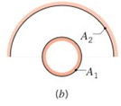
Videos
Determine F12 and F21 for the following configurations using the reciprocity theorem and other basic shape factor relations. Do not use tables or charts.
- Long duct
(a)
The shape factors.
Answer to Problem 13.1P
The shape factors are 1 and 0.212.
Explanation of Solution
Formula used:
The expression for the shape factor for surface 2 with respect to surface 1 is given as,
Here,
Calculation:
The geometrical shape is given as,
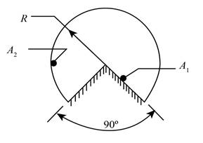
Figure (1)
The above geometry shows that inner surface completely intercepted by the outer surface. Therefore, the value of shape factors can be calculated as,
Conclusion:
Therefore, the shape factors are 1 and 0.212.
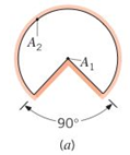
(b)
The shape factors.
Answer to Problem 13.1P
The shape factors are 0.5 and 0.25.
Explanation of Solution
Formula used:
The summation rule is given as,
The expression for the shape factor for surface 2 with respect to surface 1 is given as,
Calculation:
The geometrical shape is given as,
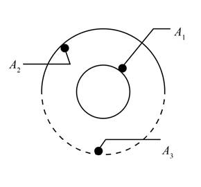
Figure (2)
The above geometry is a convex geometry, therefore the values of shape factor are obtained as,
Further obtaining the values of shape factor by summation rule as,
Further obtaining the values as,
The expression for the shape factor for surface 2 with respect to surface 1 is given as,
Conclusion:
Therefore, the shape factors are 0.5 and 0.25.
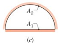
(c)
The shape factors.
Answer to Problem 13.1P
The shape factors are 1, 0.637 and 0.363.
Explanation of Solution
Formula used:
The summation rule is given as,
The expression for the shape factor for surface 2 with respect to surface 1 is given as,
The summation rule is given as,
Calculation:
The geometrical shape is given as,
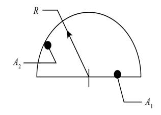
Figure (3)
The above geometry have a flat geometry at bottom, therefore the values of shape factor are obtained as,
Further obtaining the values of shape factor by summation rule as,
The expression for the shape factor for surface 2 with respect to surface 1 can be calculated as,
Further obtain the values of shape factor as,
Conclusion:
Therefore, the shape factors are 1, 0.637 and 0.363
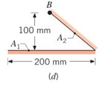
(d)
The shape factors.
Answer to Problem 13.1P
The shape factors are 0.5 and 0.707.
Explanation of Solution
Formula used:
The summation rule is given as,
The expression for the shape factor for surface 2 with respect to surface 1 is given as,
Calculation:
The geometrical shape is given as,
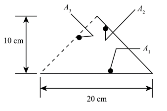
Figure (4)
The above geometry have a flat geometry at bottom, therefore the values of shape factor are obtained as,
Further obtaining the values of shape factor by summation rule as,
The expression for the shape factor for surface 2 with respect to surface 1 can be calculated as,
Conclusion:
Therefore, the shape factors are 0.5 and 0.707.
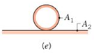
(e)
The shape factors.
Answer to Problem 13.1P
The shape factors are 0.5 and 0.
Explanation of Solution
Formula used:
The summation rule is given as,
The expression for the shape factor for surface 2 with respect to surface 1 is given as,
Calculation:
The geometrical shape is given as,
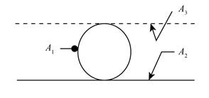
Figure (5)
The above geometry have a flat geometry at bottom, therefore the values of shape factor are obtained as,
Further obtaining the values of shape factor by summation rule as,
The expression for the shape factor for surface 2 with respect to surface 1 can be calculated as,
Conclusion:
Therefore, the shape factors are 0.5 and 0.
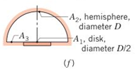
(f)
The shape factors.
Answer to Problem 13.1P
The shape factors are 1 and 0.125.
Explanation of Solution
Formula used:
The summation rule is given as,
The expression for the shape factor for surface 2 with respect to surface 1 is given as,
Calculation:
The geometrical shape is given as,
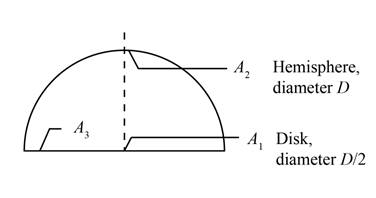
Figure (6)
The above geometry have flat disk surface, therefore the values of shape factor are obtained as,
Further obtaining the values of shape factor by summation rule as,
The expression for the shape factor for surface 2 with respect to surface 1 can be calculated as,
Conclusion:
Therefore, the shape factors are 1 and 0.25.
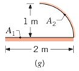
(g)
The shape factors.
Answer to Problem 13.1P
The shape factors are 0.5 and 0.637.
Explanation of Solution
Formula used:
The summation rule is given as,
The expression for the shape factor for surface 2 with respect to surface 1 is given as,
Calculation:
The geometrical shape is given as,
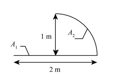
Figure (7)
The above geometry have flat disk surface, therefore the values of shape factor are obtained as,
Further obtaining the values of shape factor by summation rule as,
The expression for the shape factor for surface 2 with respect to surface 1 can be calculated as,
Conclusion:
Therefore, the shape factors are 0.5 and 0.637.
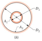
(h)
The shape factors.
Answer to Problem 13.1P
The shape factors are 1 and
Explanation of Solution
Formula used:
The summation rule is given as,
The expression for the shape factor for surface 2 with respect to surface 1 is given as,
Calculation:
The geometrical shape is given as,
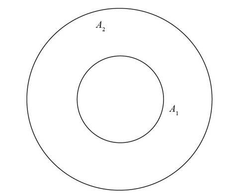
Figure (8)
The above geometry have spherical surface, therefore the values of shape factor are obtained as,
Further obtaining the values of shape factor by summation rule as,
The expression for the shape factor for surface 2 with respect to surface 1 can be calculated as,
Conclusion:
Therefore, the shape factors are 1 and
Want to see more full solutions like this?
Chapter 13 Solutions
Fundamentals of Heat and Mass Transfer
Additional Engineering Textbook Solutions
Fundamentals Of Thermodynamics
Fluid Mechanics Fundamentals And Applications
Heat and Mass Transfer: Fundamentals and Applications
Machine Elements in Mechanical Design (6th Edition) (What's New in Trades & Technology)
Thinking Like an Engineer: An Active Learning Approach (4th Edition)


- A cube of side a is cut out of another cube of side b that has a uniform density, as shown in the figure. Express the center of mass FCMof the structure using ijk unit vector notation. Set the origin at the front bottom-left corner of the figure where the dashed lines intersect. 7CM= Question Credit: OpenStax University Physics v1 a barrow_forwardQ. 2. A Figure 2 shows an isometric view of an object. Draw to a full size scale the following views in first angle projection. (a) Sectional front view, (b) Top view and (c) Sectional side view 40 SQ. Through holes 60 60- 60 180 B. 0. 30 1515arrow_forwardFigure 3 m 500 N (a) 2m B 1 of 6 Part B Draw the free-body diagram of the object (b) (Figure 2). Draw the vectors starting at the black dots. The location and orientation of the vectors will be graded. The length of the vectors will not be ► View Available Hint(s) + ΣΕ No elements selected 2 m L. B 600 N·m 3 m Select the elements from the list and add them to the canvas setting the appropriate attributes. Press ?arrow_forward
- 216 Home Works Find the Centroid for the Shaded area. [Q2] 120 150 30 90 130 4 4arrow_forwardFor the area shown in the figure below, OAC is the area of a sector with center at C and radius OC=AC=4*sqrt(2)~5.657 units. This is part 1. Part 2 is the triangle COD. Part 3 is the triangle CAB. Determine, using the method of composite areas, the second moments of area of part 1 about the y-axis [units^4]. Determine, using the method of composite areas, the second moments of area of part 2 about the y-axis [units^4]arrow_forwardSketch the object given below. It should be fully dimensional Criteria: Assume object is made of steel and sketch the following views: • plan (C view), • cross-section (Y-Y) - assume the section is exactly half on the block • right hand end elevation (B view) Draw to a scale of 1:1 (actual size in mm) Show all hidden detail and all dimensions in mm. ASSUME CROSS SECTION AA IS C EXACTLY HALF WAY THROUGH THE SHAPE B 10 15 20 130 25arrow_forward
- Draw (i) the sectional view from the front and (ii) the view from the left of the sliding support, shown in Fig. below. 2 HOLES, DIA 8 48 48 R 22 32 44 64 Fig. 4.13 Sliding supportarrow_forwardi %TV lI. N{ H.W 4.pdf > H.W/ For the the figure shown, draw the front view, top view, and side view. 25 25 125arrow_forwardConsider for the part in the figure below, a = 106, b =60 and c =112. 80 20 45 Dimensions in mm Analyze the part in order to calculate the coordinates of the centre of gravity in the (r, y, z) system of coordinates. It is assumed that the following process was following for the manufacturing process • Part 1(a cubic piece of dimension 51 x 60 x 60 is cut out of a Part 2 of dimensions 157 x 60 x 80 and then • Part 3 (triangular prism) is welded Part 2 Fill inN K IA with coordinates of centers of respective parts in mm Yi Viarrow_forward
- Draw the Orthographic projection of the given isometric view Mention the view Mention the dimensions Note : use CREO prametric 3.0arrow_forwardKINDLY SHOW THE FREE BODY DIAGRAM IN CLEAR EXPLATIONATIONarrow_forwardPlease find the Grashof classification and the Barker classification of the two four-bars: (NOTE: distances are in non-dimensional units. Can use inches or cm) P1) L1=d=4, theta1=0 degrees, L2=a=1.6, theta2=60 degrees, L3=b=5.5, L4=c=4.5 P1) L1=d=2.5, theta1=0 degrees, L2=a=2, theta2=45 degrees, L3=b=1.5, L4=c=1.5 Please also draw the four-bars to estimate the unknown angles theta3 and theta4.arrow_forward
 International Edition---engineering Mechanics: St...Mechanical EngineeringISBN:9781305501607Author:Andrew Pytel And Jaan KiusalaasPublisher:CENGAGE L