
Concept explainers
Videos
through 13.6 Calculate the reactions at points A and BFor the beams shown.
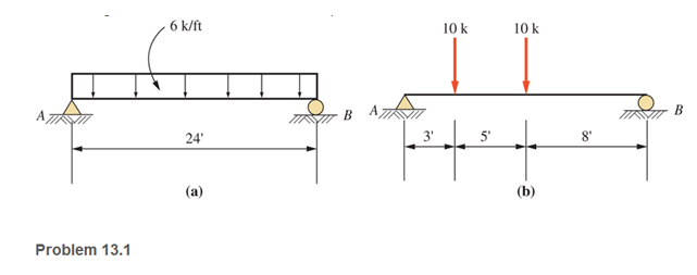
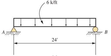
a.
The reaction forces at points A and B
Answer to Problem 13.1P
Explanation of Solution
Given:
The beam diagram and loading are given as shown below:
Concept Used:
Replacing the uniformly distribute load by a concentrated external load
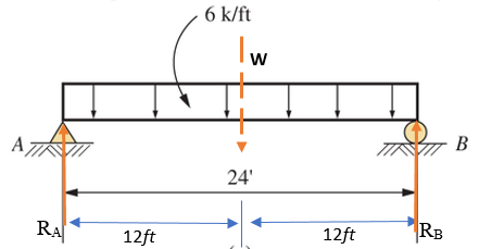
Calculation:
Taking anticlockwise moment positive, the summation of all moment of forces at point A equals to zero
For vertical equilibrium, the summation of forces in vertical direction must be zero
Conclusion:
Therefore, the reaction force at points A,
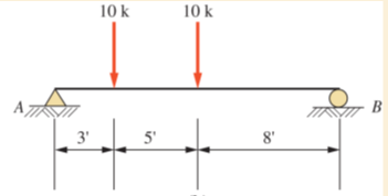
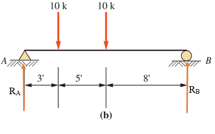
b.
The reaction forces at points A and B
Answer to Problem 13.1P
Explanation of Solution
Given:
The beam diagram and loading are given as shown below
Concept Used:
The reaction forces at point A and B are shown below in the figure and assumed to act in the upward (positive) direction
Calculation:
Taking anticlockwise moment positive, the summation of all moment of forces at point A equals to zero
For vertical equilibrium, the summation of forces in vertical direction must be zero
Conclusion:
Therefore, the forces are
Want to see more full solutions like this?
Chapter 13 Solutions
Applied Statics and Strength of Materials (6th Edition)
Additional Engineering Textbook Solutions
Engineering Mechanics: Statics & Dynamics (14th Edition)
Mechanics of Materials (10th Edition)
Mechanics of Materials
Automotive Technology: Principles, Diagnosis, and Service (5th Edition)
INTERNATIONAL EDITION---Engineering Mechanics: Statics, 14th edition (SI unit)
Thinking Like an Engineer: An Active Learning Approach (4th Edition)


- Draw the SFD and BMD for the beams loaded as shown in FigCalculate the position and magnitude of maximum bending moment and locate points of contra-flexures if any. answers must tally with those providedarrow_forwardDetermine the reactions at the supports for the prismatic beam and loading shown in Fig.arrow_forwardFor the beam shown, find the reactions at the supports and plot the shear-force and bending-moment diagrams. Label the diagrams properly and provide values at all key points.arrow_forward
- Find support reactions and create free body diagram of the following beam.arrow_forwardDraw the shear force and bending moment diagrams for the loaded beams shown? Explain breifly why the shear foce and bending moment diagrams are drawn? Note: The reactions are given.arrow_forwardFor the beam shown, find the reactions at the supports and plot the shear-force and bending-moment diagrams. Label the diagrams properly and provide values at all key points within the diagrams.arrow_forward
- Draw the free-body diagram for the following problem.The beam shown.arrow_forwardDraw the shear force diagram for the following beam and indicate various values in the diagram along with calculation for making the shear force diagram.arrow_forwardCompute the midspan value of EIy for the beam loaded as shown.arrow_forward
- Draw the SFD and BMD for the beams loaded as shown in Calculate the position and magnitude of maximum bending moment and locate points of contra-flexures if any.arrow_forwardFor the loaded beam shown below , Estimate the Reaction Values of supportsarrow_forwardAnalyze the cantilever beam shown:arrow_forward
 Elements Of ElectromagneticsMechanical EngineeringISBN:9780190698614Author:Sadiku, Matthew N. O.Publisher:Oxford University Press
 Mechanics of Materials (10th Edition)Mechanical EngineeringISBN:9780134319650Author:Russell C. HibbelerPublisher:PEARSON
 Thermodynamics: An Engineering ApproachMechanical EngineeringISBN:9781259822674Author:Yunus A. Cengel Dr., Michael A. BolesPublisher:McGraw-Hill Education
 Control Systems EngineeringMechanical EngineeringISBN:9781118170519Author:Norman S. NisePublisher:WILEY
 Mechanics of Materials (MindTap Course List)Mechanical EngineeringISBN:9781337093347Author:Barry J. Goodno, James M. GerePublisher:Cengage Learning
 Engineering Mechanics: StaticsMechanical EngineeringISBN:9781118807330Author:James L. Meriam, L. G. Kraige, J. N. BoltonPublisher:WILEY