
Mechanics of Materials (10th Edition)
10th Edition
ISBN: 9780134319650
Author: Russell C. Hibbeler
Publisher: PEARSON
expand_more
expand_more
format_list_bulleted
Concept explainers
Videos
Textbook Question
Chapter 1.2, Problem 1.1PP
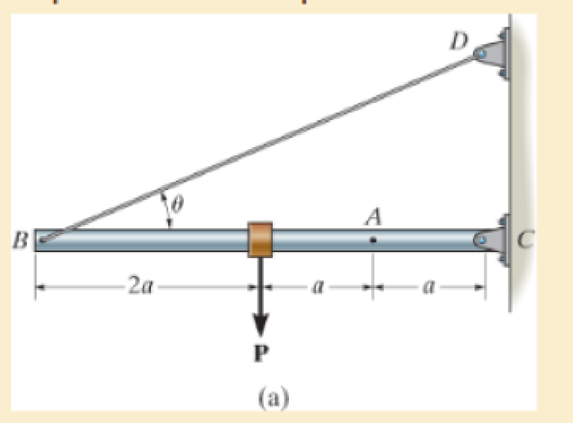
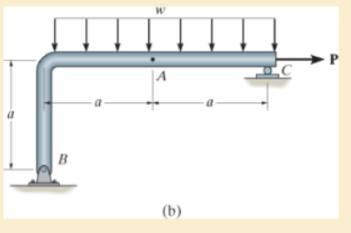
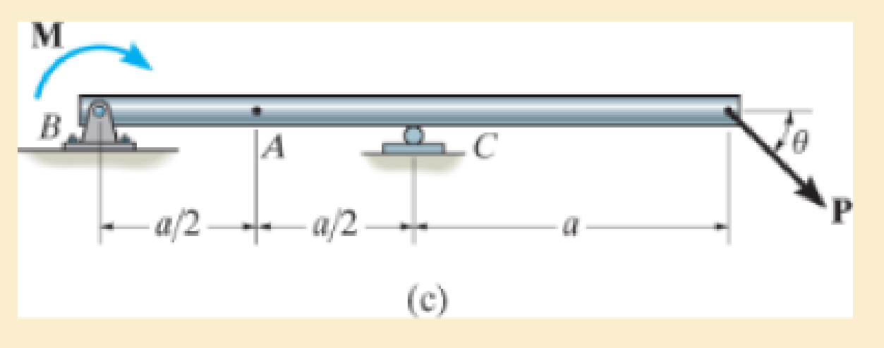
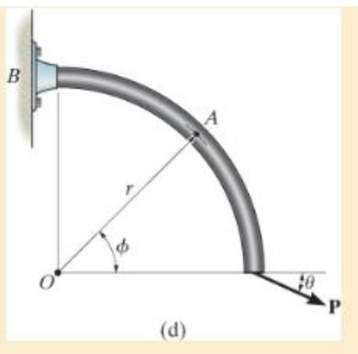
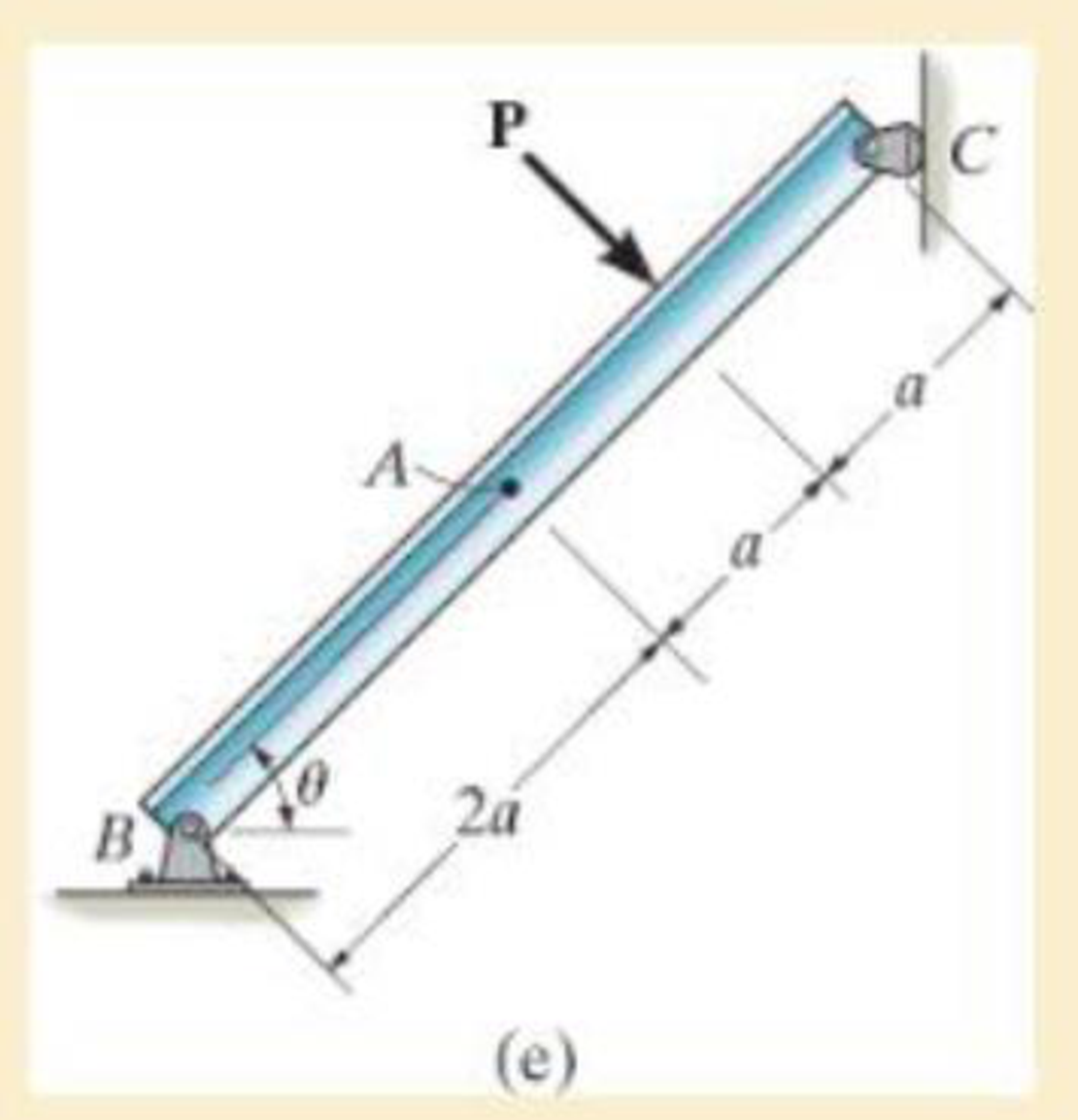
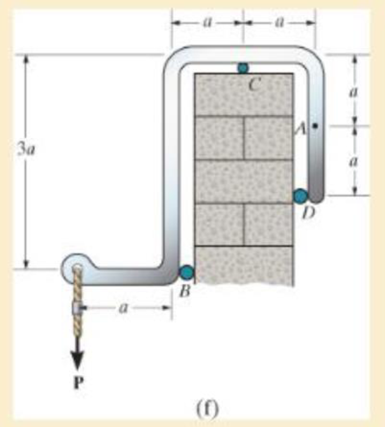
In each case, explain how to find the resultant internal loading acting on the cross section at point A. Draw all necessary free-body diagrams, and indicate the relevant equations of equilibrium. Do not calculate values. The lettered dimensions, angles, and loads are assumed to be known.
Expert Solution & Answer

Trending nowThis is a popular solution!

Students have asked these similar questions
The frame shown is supported by a pin at A and a fixed support at D. There are internal hinges/pins at
and C. Assume P = 5 kips and w = 1 kip/ft. Determine all of the external support reactions. Clearly st
true direction of each reaction.
W
10 ft
B
-8 ft-
D
2 ft
4 ft
-P
Find the reaction at A due to the uniform loading and the applied couple. The force reaction is positive if upward, negative if
downward. The moment reaction is positive if counterclockwise, negative if clockwise.
2.5 kN/m
11.1 kN-m
A
2.0 m 2.0 m
Answers:
RA =
i
kN
MA =
i
kN-m
The cable carrying 60-lb loads at B and C is held in the position shown by the horizontal force P = 80 lb applied at A. Determine the following:
Find the vertical load Ay acting on the frame at support A.
Find the vertical load By acting on the frame at pin B.
Find the horizontal load Cx acting on the frame at support C.
Find the vertical load Cy acting on the frame at support C.
Find the horizontal load Ax acting on the frame at support A.
Chapter 1 Solutions
Mechanics of Materials (10th Edition)
Ch. 1.2 - In each case, explain how to find the resultant...Ch. 1.2 - Determine the resultant internal normal force,...Ch. 1.2 - Determine the resultant internal normal force,...Ch. 1.2 - Determine the resultant internal normal force,...Ch. 1.2 - Determine the resultant internal normal force,...Ch. 1.2 - Determine the resultant internal normal force,...Ch. 1.2 - Determine the resultant internal normal force,...Ch. 1.2 - The shaft is supported by a smooth thrust bearing...Ch. 1.2 - Determine the resultant internal normal and shear...Ch. 1.2 - Determine the resultant internal loadings acting...
Ch. 1.2 - The shaft is supported by a smooth thrust bearing...Ch. 1.2 - Determine the resultant internal loadings acting...Ch. 1.2 - Determine the resultant internal loadings on the...Ch. 1.2 - Determine the resultant internal loadings at cross...Ch. 1.2 - The beam supports the distributed load shown....Ch. 1.2 - The beam supports the distributed load shown....Ch. 1.2 - The boom DF of the jib crane and the column DE...Ch. 1.2 - Determine the resultant internal loadings acting...Ch. 1.2 - Determine the resultant internal loadings acting...Ch. 1.2 - The blade of the hacksaw is subjected to a...Ch. 1.2 - The blade of the hacksaw is subjected to a...Ch. 1.2 - The beam supports the triangular distributed load...Ch. 1.2 - The beam supports the distributed load shown....Ch. 1.2 - The shaft is supported at its ends by two bearings...Ch. 1.2 - The shaft is supported at its ends by two bearings...Ch. 1.2 - The hand crank that is used in a press has the...Ch. 1.2 - Determine the resultant internal loadings acting...Ch. 1.2 - Determine the resultant internal loadings acting...Ch. 1.2 - The metal stud punch is subjected to a force of...Ch. 1.2 - Determine the resultant internal loadings acting...Ch. 1.2 - Determine the resultant internal loadings acting...Ch. 1.2 - Determine the resultant internal loadings acting...Ch. 1.2 - Determine the resultant internal loadings acting...Ch. 1.2 - The pipe has a mass of 12 kg/m. If it is fixed to...Ch. 1.2 - If the drill bit jams when the brace is subjected...Ch. 1.2 - The curved rod AD of radius r has a weight per...Ch. 1.2 - A differential element taken from a curved bar is...Ch. 1.5 - In each case, determine the largest internal shear...Ch. 1.5 - Determine the largest internal normal force in the...Ch. 1.5 - Determine the internal normal force at section A...Ch. 1.5 - The lever is held to the fixed shaft using the pin...Ch. 1.5 - The single-V butt joint transmits the force of 5...Ch. 1.5 - The uniform beam is supported by two rods AB and...Ch. 1.5 - Determine the average normal stress on the cross...Ch. 1.5 - Determine the average normal stress on the cross...Ch. 1.5 - If the 600-kN force acts through the centroid of...Ch. 1.5 - Determine the average normal stress at points A,...Ch. 1.5 - Determine the average normal stress in rod AB if...Ch. 1.5 - The supporting wheel on a scaffold is held in...Ch. 1.5 - Determine the largest intensity w of the uniform...Ch. 1.5 - The bar has a cross-sectional area A and is...Ch. 1.5 - The small block has a thickness of 0.5 in. If the...Ch. 1.5 - If the material fails when the average normal...Ch. 1.5 - If the block is subjected to a centrally applied...Ch. 1.5 - The plate has a width of 0.5 m. If the stress...Ch. 1.5 - The board is subjected to a tensile force of 200...Ch. 1.5 - The boom has a uniform weight of 600 lb and is...Ch. 1.5 - Determine the average normal stress in each of the...Ch. 1.5 - If the average normal stress in each of the...Ch. 1.5 - Determine the maximum average shear stress in pin...Ch. 1.5 - If P=5 kN, determine the average shear stress in...Ch. 1.5 - Determine the maximum magnitude P of the loads the...Ch. 1.5 - The column is made of concrete having a density of...Ch. 1.5 - The beam is supported by two rods AB and CD that...Ch. 1.5 - The beam is supported by two rods AB and CD that...Ch. 1.5 - If P = 15 kN, determine the average shear stress...Ch. 1.5 - The railcar docklight is supported by the...Ch. 1.5 - The plastic block is subjected to an axial...Ch. 1.5 - The two steel members are joined together using a...Ch. 1.5 - The bar has a cross-sectional area of 400(106) m2....Ch. 1.5 - The bar has a cross-sectional area of 400(106) m2....Ch. 1.5 - The two members used in the construction of an...Ch. 1.5 - The 2-Mg concrete pipe has a center of mass at...Ch. 1.5 - The 2-Mg concrete pipe has a center of mass at...Ch. 1.5 - The pier is made of material having a specific...Ch. 1.5 - Rods AB and BC have diameters of 4 mm and 6 mm,...Ch. 1.5 - The uniform bar, having a cross-sectional area of...Ch. 1.5 - The bar has a cross-sectional area of 400(106) m2....Ch. 1.5 - The bar has a cross-sectional area of 400(106) m2....Ch. 1.5 - The prismatic bar has a cross-sectional area A. If...Ch. 1.5 - The prismatic bar has a cross-sectional area A. If...Ch. 1.5 - The bars of the truss each have a cross-sectional...Ch. 1.5 - The bars of the truss each have a cross-sectional...Ch. 1.5 - Determine the largest load P that can be applied...Ch. 1.5 - Determine the greatest constant angular velocity ...Ch. 1.5 - The radius of the pedestal is defined by r =...Ch. 1.7 - Rods AC and BC are used to suspend the 200-kg...Ch. 1.7 - If it is subjected to double shear, determine the...Ch. 1.7 - Determine the maximum average shear stress...Ch. 1.7 - If each of the three nails has a diameter of 4 mm...Ch. 1.7 - The strut is glued to the horizontal member at...Ch. 1.7 - Determine the maximum average shear stress...Ch. 1.7 - If the eyebolt is made of a material having a...Ch. 1.7 - If the bar assembly is made of a material having a...Ch. 1.7 - Determine the maximum force P that can be applied...Ch. 1.7 - The pin is made of a material having a failure...Ch. 1.7 - If the bolt head and the supporting bracket are...Ch. 1.7 - Six nails are used to hold the hanger at A against...Ch. 1.7 - If A and B are both made of wood and are 38 in....Ch. 1.7 - Prob. 1.70PCh. 1.7 - The connection is made using a bolt and nut and...Ch. 1.7 - The tension member is fastened together using two...Ch. 1.7 - The steel swivel bushing in the elevator control...Ch. 1.7 - The spring mechanism is used as a shock absorber...Ch. 1.7 - Determine the size of square bearing plates A and...Ch. 1.7 - Determine the maximum load P that can be applied...Ch. 1.7 - Determine the required diameter of the pins at A...Ch. 1.7 - If the allowable tensile stress for wires AB and...Ch. 1.7 - If the allowable tensile stress for wires AB and...Ch. 1.7 - The cotter is used to hold the two rods together....Ch. 1.7 - Determine the required diameter of the pins at A...Ch. 1.7 - The steel pipe is supported on the circular base...Ch. 1.7 - The boom is supported by the winch cable that has...Ch. 1.7 - The boom is supported by the winch cable that has...Ch. 1.7 - The assembly consists of three disks A, B, and C...Ch. 1.7 - The two aluminum rods support the vertical force...Ch. 1.7 - The two aluminum rods AB and AC have diameters of...Ch. 1.7 - Determine the required minimum thickness t of...Ch. 1.7 - Determine the maximum allowable load P that can be...Ch. 1.7 - The compound wooden beam is connected together by...Ch. 1.7 - The hanger is supported using the rectangular pin....Ch. 1.7 - The hanger is supported using the rectangular pin....Ch. 1.7 - The rods AB and CD are made of steel. Determine...Ch. 1.7 - The aluminum bracket A is used to support the...Ch. 1.7 - If the allowable tensile stress for the bar is...Ch. 1.7 - The bar is connected to the support using a pin...Ch. 1 - The beam AB is pin supported at A and supported by...Ch. 1 - The long bolt passes through the 30-mm-thick...Ch. 1 - Determine the required thickness of member BC to...Ch. 1 - The circular punch B exerts a force of 2 kN on the...Ch. 1 - Determine the average punching shear stress the...Ch. 1 - The 150 mm by 150 mm block of aluminum supports a...Ch. 1 - The yoke-and-rod connection is subjected to a...Ch. 1 - The cable has a specific weight (weight/volume)...
Additional Engineering Textbook Solutions
Find more solutions based on key concepts
4.12 Calculate the force in each cable for the suspended weight shown.
Applied Statics and Strength of Materials (6th Edition)
The moment of force about point O.
Engineering Mechanics: Statics & Dynamics (14th Edition)
In each case, determine the moment of the force about point O. Prob. P3-1
Statics and Mechanics of Materials (5th Edition)
14. When one tries to stop a car, both the reaction time of the driver and the braking time must be considered....
Thinking Like an Engineer: An Active Learning Approach (4th Edition)
Determine the magnitude of the horizontal force F = Fi acting on the handle of the wrench so that this force pr...
INTERNATIONAL EDITION---Engineering Mechanics: Statics, 14th edition (SI unit)
ICA 7-1
Express the following values using scientific notation, engineering notation, and using an appropriate ...
Thinking Like an Engineer: An Active Learning Approach (3rd Edition)
Knowledge Booster


Learn more about
Need a deep-dive on the concept behind this application? Look no further. Learn more about this topic, mechanical-engineering and related others by exploring similar questions and additional content below.Similar questions
- 5. The three bars are pinned together and subjected to the load P. If each bar has a cross-sectional area A, length L, and is made from an elastic perfectly plastic material, for which the yield stress is oy, determine the largest load (ultimate load) that can be supported by the bars, i.e., the load P that causes all the bars to yield. Also, what is the horizontal displacement of point A when the load reaches its ultimate value? The modulus of elasticity is E.arrow_forward5. The three bars are pinned together and subjected to the load P. If each bar has a cross-sectional area A, length L, and is made from an elastic perfectly plastic material, for which the yield stress is oy, determine the largest load (ultimate load) that can be supported by the bars, i.e., the load P that causes all the bars to yield. Also, what is the horizontal displacement of point A when the load reaches its ultimate value? The modulus of elasticity is E. C L.arrow_forwardAssume the equilibrium equations below. x-equation: A - BE() + CD = 0 y-equation: Ay - BE() = 0 Moment about point A: BE··6-CD-10 = 0 Use CD from the original diagram. Determine the support reaction in lb at A in the x-direction. (Give the answer to 0 decimal places.) .arrow_forward
- The shear strain is calculated using the torque and the polar moment of inertia. Select one: a. True b. Falsearrow_forwardA bent pipe is connected by a thrust bearing and a cable as shown. If a Force, F = 184 lb, is applied, what are the reactions at the thrust bearing and in the cable. The dimensions shown are a = 8.7 ft, b = 6.4 ft, and c = 4.5 ft. y Narrow_forwardYour answer is partially correct. The 410-kg uniform beam is subjected to the three external loads shown. Compute the reactions at the support point O. The x-y plane is vertical. Positive values are to the right, up, and counterclockwise. y 37 3.0 kN 39 kN m A B 5.8 kN -1.2 m- 1.8 m 1.8 m Answers: O, = 1.805 kN O, = 0.614 kN Mo = i 22173.54 kN-m eTextbook and Media Attempts: unlimited Submit Answer Save for Laterarrow_forward
- For the following question, choose the correct answers Section Determine the components of the support reactions at the fixed support A on the cantilevered beam. 6 kN 30° 30° 1.5 m A 1.5 m 1.5 m- 4 kN =The x component of the reaction at A is Ax 8.46 kN 3.46 kN -9 kN -3.46 kN Oarrow_forwardThe 460-kg uniform beam is subjected to the three external loads shown. Compute the reactions at the support point O. The x-y plane is vertical. Positive values are to the right, up, and counterclockwise. 0 1.2 m Answers: Ox Oy = i Mo= i i A 6.1 KN 1.6 m 19 kN.m B kN kN 1.6 m kN-m 20 C 2.7 KN -1xarrow_forwardThe member is supported by a square rod which fits loosely through the smooth square hole of the attached collar at A and by a roller at B. The member is subjected to the forces Fi = 300 N, F2 = 450 N, and F3 = 600 N. (Figure 1) Determine the components of the reaction force of the support at A using scalar notation. Express your answers using three significant figures separated by comma. Ar, Ay = -300,-450 N Submit Previous Answers v Correct Part C Determine the components of moment of the reaction at A using scalar notation. Figure 1 of 1 Express your answers using three significant figures separated by commas. vec (MA)=: (MA)y, (MA): =- 900,100, – 1350 N.m B 1 m 2 m Submit Previous Answers Request Answer 2 m X Incorrect; Try Again; 4 attempts remaining < Return to Assignment Provide Feedback 圓arrow_forward
- explain how to find the resultant internal loading acting on the cross section at point A. Draw all necessary free-body diagrams, and indicate the relevant equations of equilibrium. Do not calculate values The lettered dimensions, angles, and loads are assumed to be known. P7-1.arrow_forward5) Use the method of sections to find the true magnitude and direction in bar DB of the truss. Hint( Joint C is in equilibrium) В 45° F. 4' E 4' -100 Ibsarrow_forwardThe shaft of radius c is subjected to a distributed torque t, measured as torque>length of shaft. Determine the reactions at the fixed supports A and B.arrow_forward
arrow_back_ios
SEE MORE QUESTIONS
arrow_forward_ios
Recommended textbooks for you
 Elements Of ElectromagneticsMechanical EngineeringISBN:9780190698614Author:Sadiku, Matthew N. O.Publisher:Oxford University Press
 Mechanics of Materials (10th Edition)Mechanical EngineeringISBN:9780134319650Author:Russell C. HibbelerPublisher:PEARSON
 Thermodynamics: An Engineering ApproachMechanical EngineeringISBN:9781259822674Author:Yunus A. Cengel Dr., Michael A. BolesPublisher:McGraw-Hill Education
 Control Systems EngineeringMechanical EngineeringISBN:9781118170519Author:Norman S. NisePublisher:WILEY
 Mechanics of Materials (MindTap Course List)Mechanical EngineeringISBN:9781337093347Author:Barry J. Goodno, James M. GerePublisher:Cengage Learning
 Engineering Mechanics: StaticsMechanical EngineeringISBN:9781118807330Author:James L. Meriam, L. G. Kraige, J. N. BoltonPublisher:WILEY
Elements Of Electromagnetics
Mechanical Engineering
ISBN:9780190698614
Author:Sadiku, Matthew N. O.
Publisher:Oxford University Press
Mechanics of Materials (10th Edition)
Mechanical Engineering
ISBN:9780134319650
Author:Russell C. Hibbeler
Publisher:PEARSON
Thermodynamics: An Engineering Approach
Mechanical Engineering
ISBN:9781259822674
Author:Yunus A. Cengel Dr., Michael A. Boles
Publisher:McGraw-Hill Education
Control Systems Engineering
Mechanical Engineering
ISBN:9781118170519
Author:Norman S. Nise
Publisher:WILEY
Mechanics of Materials (MindTap Course List)
Mechanical Engineering
ISBN:9781337093347
Author:Barry J. Goodno, James M. Gere
Publisher:Cengage Learning
Engineering Mechanics: Statics
Mechanical Engineering
ISBN:9781118807330
Author:James L. Meriam, L. G. Kraige, J. N. Bolton
Publisher:WILEY
EVERYTHING on Axial Loading Normal Stress in 10 MINUTES - Mechanics of Materials; Author: Less Boring Lectures;https://www.youtube.com/watch?v=jQ-fNqZWrNg;License: Standard YouTube License, CC-BY