
Concept explainers
Videos
Find the expressions for voltages
Answer to Problem 63E
The expressions for nodal voltages
Explanation of Solution
Given data:
Formula used:
Consider the general expression for inductive impedance.
Here,
Consider the general expression for capacitive impedance.
Here,
Calculation:
Refer to Figure in the respective question.
From Figure , at
Substitute
Substitute
Case 1:
Consider
Substitute
Substitute
Redraw Figure, as shown in Figure 1.
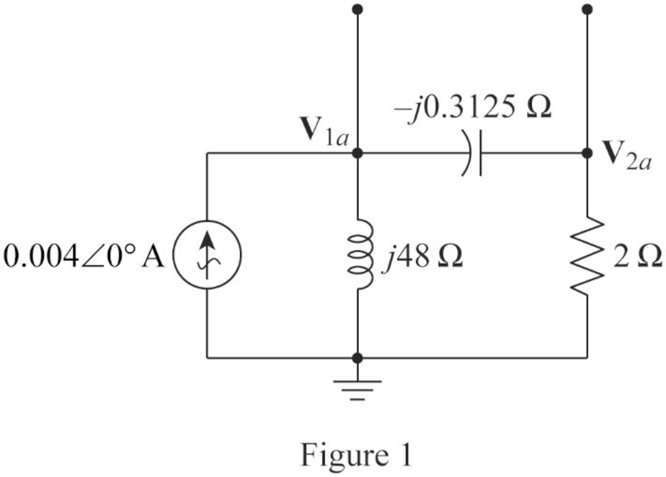
Apply KCL at node
Simplify the equation as follows.
Apply KCL at node
Write the equations (1) and (2) in matrix form.
Write the Matlab code to solve equation (3)
A = [(i*3.1792) (-i*3.2); (-i*3.2) (0.5+i*3.2)];
B = [(0.004+i*0);(0)];
C = inv(A)*B
Matlab Output:
C =
0.0080908 - 0.0009194i
0.0080382 + 0.0003366i
Polar equations of node voltages are as follows.
Case 2:
Consider
Substitute
Substitute
Redraw Figure, as shown in Figure 2.
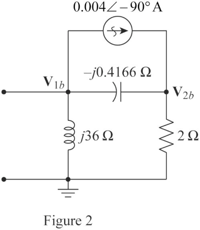
Apply KCL at node
Simplify the equation as follows.
Apply KCL at node
Write the equations (4) and (5) in matrix form.
Write the Matlab code to solve equation (3)
A = [(i*2.373) (-i*2.4); (0.5+i*2.4) (-i*2.4)];
B = [(i*0.004);(-i*0.004)];
C = inv(A)*B
Matlab Output:
C =
-0.000861 - 0.015953i
-0.002518 - 0.015774i
Polar equations of node voltages are as follows.
Find nodal voltage
Substitute
Convert
Find nodal voltage
Substitute
Conclusion:
Thus, the expressions for nodal voltages
Want to see more full solutions like this?
Chapter 10 Solutions
Loose Leaf for Engineering Circuit Analysis Format: Loose-leaf


- Given that us(t)=90sin(240t – 40°) V in the given figure. Determine i¸(t). 10 92 30 Ω ww www Vs (t) The current ix (t) = Im sin(240t+0) A, where: Im 0 = + = 0.2 H 0.5 mF A (Calculate to 2 decimal places) deg (Calculate to 2 decimal places) Please report your answer so the magnitude is positive and all angles are in the range of negative 180 degrees to positive 180 degrees.arrow_forward10:45 1 .III 5G Done Series Parallel Practice Problems 1 of 7 Series/Parallel Circuits Practice Problems For each circuit provided, fully solve and complete the associated table. 1. 12 GOV RS 2000 R4 3000 R3 350 R(Q) V(v) I(A) P(W) 22222 300 300 35 15 200 Total R(Q) V(v) I(A) P(W)arrow_forwardCalculate current of inductor and voltage of capacitor in transient state after turning on the switch in the circuit of Fig. 10.25. Assume: R=5Ω, C=100μF, L=1H, e1(t)=10V, e2(t)=10V.arrow_forward
- Homework (1) For the circuit shown in fig.(*), find the rms value of i, VR, and VL UR e = 63.60 + 100.0 sin wt – 42.40 sin(2wt + 90°) R = 60 L = 0.1 HU 0=377arrow_forward42. Find V in Fig. 10.55 if the box contains (a) 3 2 in series with 2 mH; (b) 3 2 in series with 125 µF; (c) 3 2, 2 mH, and 125 µF in series; (d) 3 2, 2 mH, and 125 µF in series, but w = 4 krad/s.arrow_forwardProblem 10.003 - Nodal analysis in circuits with voltage sources Calculate the output voltage vo(t) of the circuit given below, where i(t) = 3 cos 4t A. Please report your answer so the magnitude is positive and all angles are in the range of negative 180 degrees to positive 180 degrees. 492 2 H 16 sin 4t V + + Vo 1/22 F 192 The output voltage of the circuit is vo(t) www 6Ω ✓✔ (Click to select) t+ sin COS °)) V.arrow_forward
- V=225V, 20° Q R= 150, L= 125H H 7 1 C= F and 1000 f= 50Hz V R L Give the answers to one decimal place. Calculate the circuit's a) The angular frequency: rad/s b) The total impedance (give the answer as the absolute value): c) The sum of the voltages of the circuit's components R, L and C (give the answer as the absolute value):arrow_forward0198% 10:15 Leila Hammadi B... 1 minute ago Given the following circuit with Is=40<30° mA Is 12:1 V 10002 Select one: O a. V, 120<60° V b. V,-480<30° V C. None of these d. V,-480<-30° V < O Oarrow_forwardQuestion 4 Giving the following tank circuit, if L= 50 mH, R=5Q and C=15µF. The approximate value of w, is 1. C 314.7 1150.36 None of the answers 1989.97arrow_forward
- For the component shown with the given voltage and current reference directions, the voltage across and the current through the component are plotted. Determine the total amount of energy consumed by the component. +. Voltage Current 2 V - 4 A 1V + 2 A + Time Time 5 s 10 s 5 s 10 s -20 J -60 J 20 J 60 Jarrow_forwardGive the following equivalent circuits for an RLC system: i0 20 4 H 10 sin(21 – 30°) V 102-30° -j3 (a) (b) Determine the average and reactive power delivered by the source.arrow_forward16 0 t = 0' 4 V 0.5 H 312.5 рF Vs(t) = 4 V Constant voltage source Ve(t) = Vo(t) Voltage across capacitor ic(t) Current flowing through the сараcitor inductance voltage across VL(t) ilt) inductance Inductance current VR(t) Voltage across resistor İR(t) Current flowing through resistor Vc(0) 3 V Capacitor voltage at time t=0 After the switch has been open long enough, it is closed at t=0. Which of the following is the Laplace transform of the current ic(t)? ir(t)? vr(t)=? Vc(t)=?arrow_forward
 Introductory Circuit Analysis (13th Edition)Electrical EngineeringISBN:9780133923605Author:Robert L. BoylestadPublisher:PEARSON
 Delmar's Standard Textbook Of ElectricityElectrical EngineeringISBN:9781337900348Author:Stephen L. HermanPublisher:Cengage Learning
 Programmable Logic ControllersElectrical EngineeringISBN:9780073373843Author:Frank D. PetruzellaPublisher:McGraw-Hill Education
 Fundamentals of Electric CircuitsElectrical EngineeringISBN:9780078028229Author:Charles K Alexander, Matthew SadikuPublisher:McGraw-Hill Education
 Electric Circuits. (11th Edition)Electrical EngineeringISBN:9780134746968Author:James W. Nilsson, Susan RiedelPublisher:PEARSON
 Engineering ElectromagneticsElectrical EngineeringISBN:9780078028151Author:Hayt, William H. (william Hart), Jr, BUCK, John A.Publisher:Mcgraw-hill Education,