
Mechanics of Materials (MindTap Course List)
9th Edition
ISBN: 9781337093347
Author: Barry J. Goodno, James M. Gere
Publisher: Cengage Learning
expand_more
expand_more
format_list_bulleted
Videos
Textbook Question
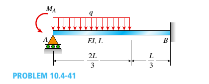
Chapter 10, Problem 10.4.41P
Find an expression for required moment MA(in terms of q and L) that will result in rotation
Expert Solution & Answer
Want to see the full answer?
Check out a sample textbook solution
Students have asked these similar questions
Find the shear force and bending moment at points B and D. Note: B lies just to the right of the
150 lbf force and D is just to the right of the bearing at C. The bearing at A is a thrust bearing,
while the bearing at C is a journal bearing.
150 lb
A
Answer:
VB = -100 lbf
MB = 750 lbf in
VD = 75lbf
Mp = -750 lbf in
I
15 in.
B
15 in.
C.
D
75 lb
10 in.
3. For the structure carrying a uniform load of 4 kN/ m, compute the internal axial force, shear force, and
Answer: Vc = 2 kN, Mc = 4 kNm, Nc = 24 kN
bending moment at point C in the beam.
4 kN/ m
|C
B
3 m
2 m
-2 m
2 m
Find the reaction forces at pin A and smooth rocker at B. Assume F = 15 kN.
Ax =
Ay =
B =
y
F
A
30°
6 m
2 m
%3D
Chapter 10 Solutions
Mechanics of Materials (MindTap Course List)
Ch. 10 - A propped cantilever steel beam is constructed...Ch. 10 - A fixed-end b earn is subjected to a point load at...Ch. 10 - A propped cantilever beam AB of a length L is...Ch. 10 - A fixed-end beam AB of a length L supports a...Ch. 10 - A cantilever beam AB of a length L has a fixed...Ch. 10 - A cantilever beam of a length L and loaded by a...Ch. 10 - A cantilever beam has a length L and is loaded by...Ch. 10 - A propped cantilever beam of a length L is loaded...Ch. 10 - A propped cantilever beam of a length L is loaded...Ch. 10 - A fixed-end beam of a length L is loaded by a...
Ch. 10 - A fixed-end b earn of a length L is loaded by a...Ch. 10 - A fixed-end beam of a length L is loaded by...Ch. 10 - A counterclockwise moment M0acts at the midpoint...Ch. 10 - A propped cantilever beam of a length L is loaded...Ch. 10 - A propped cantilever beam is subjected to uniform...Ch. 10 - Repeat Problem 10.3-15 using L = 3.5 m, max = 3...Ch. 10 - A two-span, continuous wood girder (E = 1700 ksi)...Ch. 10 - A fixed-end beam AB carries point load P acting at...Ch. 10 - A fixed-end beam AB supports a uniform load of...Ch. 10 - -4-4 A cantilever beam is supported at B by cable...Ch. 10 - A propped cantilever beam AB of a length L carries...Ch. 10 - A beam with a sliding support at B is loaded by a...Ch. 10 - A propped cantilever beam of a length 2L with a...Ch. 10 - The continuous frame ABC has a pin support at /l,...Ch. 10 - The continuous frame ABC has a pin support at A,...Ch. 10 - Beam AB has a pin support at A and a roller...Ch. 10 - The continuous frame ABCD has a pin support at B:...Ch. 10 - Two flat beams AB and CD, lying in horizontal...Ch. 10 - -4-13 A propped cantilever beam of a length 2L is...Ch. 10 - A propped cantilever beam of a length 2L is loaded...Ch. 10 - Determine the fixed-end moments (MAand MB) and...Ch. 10 - A continuous beam ABC wit h two unequal spans, one...Ch. 10 - Beam ABC is fixed at support A and rests (at point...Ch. 10 - A propped cantilever beam has flexural rigidity EI...Ch. 10 - A triangularly distributed 1oad with a maximum...Ch. 10 - A fixed-end beam is loaded by a uniform load q =...Ch. 10 - Uniform load q = 10 lb/ft acts over part of the...Ch. 10 - A propped cantilever beam with a length L = 4 m is...Ch. 10 - A cant i levé r b ea m i s supported by a tie rod...Ch. 10 - The figure shows a nonprismatic, propped...Ch. 10 - A beam ABC is fixed at end A and supported by beam...Ch. 10 - A three-span continuous beam A BCD with three...Ch. 10 - A beam rests on supports at A and B and is loaded...Ch. 10 - A propped cantilever beam is subjected to two...Ch. 10 - A propped cantilever beam is loaded by a...Ch. 10 - A fixed-end beam AB of a length L is subjected to...Ch. 10 - A temporary wood flume serving as a channel for...Ch. 10 - Two identical, simply supported beams AB and CD...Ch. 10 - The cantilever beam AB shown in the figure is an...Ch. 10 - The beam AB shown in the figure is simply...Ch. 10 - The continuous frame ABC has a fixed support at A,...Ch. 10 - The continuous frame ABC has a pinned support at...Ch. 10 - A wide-flange beam ABC rests on three identical...Ch. 10 - A fixed-end beam AB of a length L is subjected to...Ch. 10 - A beam supporting a uniform load of intensity q...Ch. 10 - A thin steel beam AB used in conjunction with an...Ch. 10 - Find an expression for required moment MA(in terms...Ch. 10 - Repeat Problem 10.4-41 for the loading shown in...Ch. 10 - A propped cantilever beam is loaded by two...Ch. 10 - A cable CD of a length H is attached to the third...Ch. 10 - A propped cantilever beam, fixed at the left-hand...Ch. 10 - Solve t he preceding problem by integrating the...Ch. 10 - A two-span beam with spans of lengths L and L/3 is...Ch. 10 - Solve the preceding problem by integrating the...Ch. 10 - Assume that the deflected shape of a beam AB with...Ch. 10 - (a) A simple beam AB with length L and height h...
Knowledge Booster


Learn more about
Need a deep-dive on the concept behind this application? Look no further. Learn more about this topic, mechanical-engineering and related others by exploring similar questions and additional content below.Similar questions
- A bending moment due to load applied on the head of femur bone which is offset by a distance (x= 50 mm) off the bone center for a person standing in relaxation.His weight is 70kg.1. Find the maximum bending stress induced due to the weight and compare it to the maximum comp. stress. R= 20mm t= 12mm.2. Draw the expression for the second moment (I) basing on min-wall hollow cylinder.3. Find the principal stress σ1, σ2, τx1y1, and the angle θp for point C and D shown.arrow_forwardThe beam shown below is supported by rollers at A and B, and by a pin at C. If EI is constant over the length of the beam, find the reaction forces at A, B, and C. 15 kip AT 6 ft B_ 6 ft 12 ft 3 kip/ft Carrow_forwardFind Δ v, and theta, as assigned, at the center of the span due to the applied loads shown in the figures. El is constant. Consider flexural deformation only.arrow_forward
- 3- Draw the shear force and bending moment of the beam. You have to find their equation, and your diagram without calculation is not acceptable.(41) 20 kN 1.5 kN/m B 1m 1 m 4 marrow_forwardUsing Castigliano's second theorem, Find Δ v, and theta, as assigned, at the center of the span due to the applied loads shown in the figures. El is constant. Consider flexural deformation only.arrow_forwardwith the following modifications: Add an additional force P = 20kN acting downwards at point Barrow_forward
- Mo = M-400×0.15cos30-320x 0.3 = 0 160 mm 400 N M = 148 Nm CCW Example : Replace the three forces acting on the bent beam by a single equivalent force R. Specify the distance x from the point O in which the line of action of R passes. 200 N 160 N 250 mm 250 mm 250 mm 125 mm 240 Narrow_forwardModulus E of elasticity, for the ACB beam with inertia I; a- Find the elastic curve equation with the singularity equation. b- Find the reaction forces at Point A. c- Find the reaction force at Point B. (2/3) W 2W A W -L/2 Larrow_forwardA beam supports both a uniform distributed load and a concentrated force, as shown in the figure below. The uniform distributed load has a magnitude q 400 lb/ft and extends across the entire beam. The T concentrated force has a magnitude F 14 kip and acts LF = 17 ft to the right of point A. The beam has an overall length L = 24 ft, and is held in equilibrium by a pin at point A and a roller at point B. Neglect the height and weight of the beam for this analysis. Determine the internal shear force (V) and internal bending moment (M) at the following locations: F A V₁ = 4.88 M. L₁ 20 L Note: Express your answers following the standard sign convention for internal shear force and internal bending moment, as described in the textbook. (a) A point x₁ = 10 ft to the right of point A. kip ? q kin ft Barrow_forward
- 1 b(x) = 96-6x lb/in he = 12 in 2 X Determine the equivalent nodal forces for the axially distributed loading acting on the bar elements. Use linear finite element shape functions; let x = 0.arrow_forward화 F 1/2 √2/2 я/ TE use symmetry to f the r Find reactions and draw moment diagram using unit load w/ method of constant deformationsarrow_forwardIn the figure given below load and moment effects from the mid point of the fixed beam from both sides. Find the displacement and reaction forces.arrow_forward
arrow_back_ios
SEE MORE QUESTIONS
arrow_forward_ios
Recommended textbooks for you
 Mechanics of Materials (MindTap Course List)Mechanical EngineeringISBN:9781337093347Author:Barry J. Goodno, James M. GerePublisher:Cengage Learning
Mechanics of Materials (MindTap Course List)
Mechanical Engineering
ISBN:9781337093347
Author:Barry J. Goodno, James M. Gere
Publisher:Cengage Learning
Everything About TRANSVERSE SHEAR in 10 Minutes!! - Mechanics of Materials; Author: Less Boring Lectures;https://www.youtube.com/watch?v=4x0E9yvzfCM;License: Standard Youtube License