
Loose Leaf for Engineering Circuit Analysis Format: Loose-leaf
9th Edition
ISBN: 9781259989452
Author: Hayt
Publisher: Mcgraw Hill Publishers
expand_more
expand_more
format_list_bulleted
Videos
Textbook Question
Chapter 15.1, Problem 1P
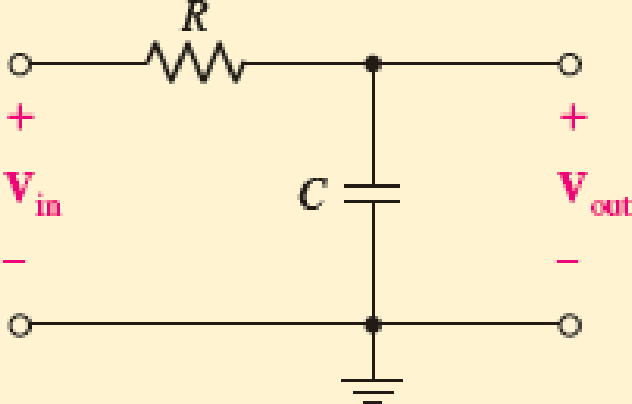
Write an expression for the transfer function of the RC network in Fig 15.1 after switching the positions of the resistor and capacitor such that Vout is now the voltage drop across the resistor. Evaluate at ω = 0, ω = ω0 = 1/CR, and ω = ∞.
FIGURE 15.1 Example RC network, the transfer function of which is of interest.
Expert Solution & Answer
Want to see the full answer?
Check out a sample textbook solution
Students have asked these similar questions
For the parabola input of the closed loop system given below, the steady state error is ess = 0.001 Gc What should be the
transfer function of the block?
A=23
B=432
X=46
y=216
Y(s)
|(s+ A)(s+X)
R(s)
B
Gc
Y
Question 6
R
R1
C
Find the time constant for the circuit shown above. Where the circuit parameters are : R1=10, C=6,
R=10. Round your answer to 3 decimal places.
(Hint: find the transfer function then get the characteristic equation, then get the roots and
then find the time constant)
Consider the following active filter circuit. (C1=2u F, R1=5K2, C2=2.5µuF, R2=4KQ)
Zf
C2
R2
R1
と
+.
--
Chapter 15 Solutions
Loose Leaf for Engineering Circuit Analysis Format: Loose-leaf
Ch. 15.1 - Write an expression for the transfer function of...Ch. 15.2 - Calculate HdB at = 146 rad/s if H(s) equals (a)...Ch. 15.2 - Prob. 3PCh. 15.2 - Draw the Bode phase plot for the transfer function...Ch. 15.2 - Construct a Bode magnitude plot for H(s) equal to...Ch. 15.2 - Draw the Bode phase plot for H(s) equal to (a)...Ch. 15.2 - Prob. 7PCh. 15.3 - A parallel resonant circuit is composed of the...Ch. 15.3 - Prob. 9PCh. 15.4 - A marginally high-Q parallel resonant circuit has...
Ch. 15.5 - A series resonant circuit has a bandwidth of 100...Ch. 15.6 - Referring to the circuit of Fig. 15.25a, let R1 =...Ch. 15.6 - Prob. 13PCh. 15.6 - Prob. 14PCh. 15.6 - The series combination of 10 and 10 nF is in...Ch. 15.7 - A parallel resonant circuit is defined by C = 0.01...Ch. 15.8 - Design a high-pass filter with a cutoff frequency...Ch. 15.8 - Design a bandpass filter with a low-frequency...Ch. 15.8 - Design a low-pass filter circuit with a gain of 30...Ch. 15 - For the RL circuit in Fig. 15.52, (a) determine...Ch. 15 - For the RL circuit in Fig. 15.52, switch the...Ch. 15 - Examine the series RLC circuit in Fig. 15.53, with...Ch. 15 - For the circuit in Fig. 15.54, (a) derive an...Ch. 15 - For the circuit in Fig. 15.55, (a) derive an...Ch. 15 - For the circuit in Fig. 15.56, (a) determine the...Ch. 15 - For the circuit in Fig. 15.57, (a) determine the...Ch. 15 - Sketch the Bode magnitude and phase plots for the...Ch. 15 - Use the Bode approach to sketch the magnitude of...Ch. 15 - If a particular network is described by transfer...Ch. 15 - Use MATLAB to plot the magnitude and phase Bode...Ch. 15 - Determine the Bode magnitude plot for the...Ch. 15 - Determine the Bode magnitude and phase plot for...Ch. 15 - Prob. 15ECh. 15 - Prob. 16ECh. 15 - For the circuit of Fig. 15.56, construct a...Ch. 15 - Construct a magnitude and phase Bode plot for the...Ch. 15 - For the circuit in Fig. 15.54, use LTspice to...Ch. 15 - For the circuit in Fig. 15.55, use LTspice to...Ch. 15 - Prob. 21ECh. 15 - A certain parallel RLC circuit is built using...Ch. 15 - A parallel RLC network is constructed using R = 5...Ch. 15 - Prob. 24ECh. 15 - Delete the 2 resistor in the network of Fig....Ch. 15 - Delete the 1 resistor in the network of Fig....Ch. 15 - Prob. 28ECh. 15 - Prob. 29ECh. 15 - Prob. 30ECh. 15 - A parallel RLC network is constructed with a 200 H...Ch. 15 - Prob. 32ECh. 15 - A parallel RLC circuit is constructed such that it...Ch. 15 - Prob. 34ECh. 15 - Prob. 35ECh. 15 - An RLC circuit is constructed using R = 5 , L = 20...Ch. 15 - Prob. 37ECh. 15 - Prob. 38ECh. 15 - For the network of Fig. 15.25a, R1 = 100 , R2 =...Ch. 15 - Assuming an operating frequency of 200 rad/s, find...Ch. 15 - Prob. 41ECh. 15 - Prob. 42ECh. 15 - For the circuit shown in Fig. 15.64, the voltage...Ch. 15 - Prob. 44ECh. 15 - Prob. 45ECh. 15 - Prob. 46ECh. 15 - The filter shown in Fig. 15.66a has the response...Ch. 15 - Prob. 48ECh. 15 - Examine the filter for the circuit in Fig. 15.68....Ch. 15 - Examine the filter for the circuit in Fig. 15.69....Ch. 15 - (a)Design a high-pass filter with a corner...Ch. 15 - (a) Design a low-pass filter with a break...Ch. 15 - Prob. 53ECh. 15 - Prob. 54ECh. 15 - Design a low-pass filter characterized by a...Ch. 15 - Prob. 56ECh. 15 - The circuit in Fig. 15.70 is known as a notch...Ch. 15 - (a) Design a two-stage op amp filter circuit with...Ch. 15 - Design a circuit which removes the entire audio...Ch. 15 - Prob. 61ECh. 15 - If a high-pass filter is required having gain of 6...Ch. 15 - (a) Design a second-order high-pass Butterworth...Ch. 15 - Design a fourth-order high-pass Butterworth filter...Ch. 15 - (a) Design a Sallen-Key low-pass filter with a...Ch. 15 - (a) Design a Sallen-Key low-pass filter with a...Ch. 15 - A piezoelectric sensor has an equivalent circuit...Ch. 15 - Design a parallel resonant circuit for an AM radio...Ch. 15 - The network of Fig. 15.72 was implemented as a...Ch. 15 - Determine the effect of component tolerance on the...
Additional Engineering Textbook Solutions
Find more solutions based on key concepts
Electric power systems provide energy in a variety of commercial and industrial settings. Make a list of system...
Principles and Applications of Electrical Engineering
Design an ideal inverting op-amp circuit such that the voltage gain is Av=25 . The maximum current in any resis...
Microelectronics: Circuit Analysis and Design
For the “tank” circuit in Fig. 14.79, find the resonant frequency.
Figure 14.79
For Probs. 14.39, 14.71, and 1...
Fundamentals of Electric Circuits
Find I0 and I1 in the circuit in Fig.P2.12.
Basic Engineering Circuit Analysis
Analog Voltmeter Design Figure P2-98(a) shows a voltmeter circuit consisting of a D'Arsonval meter, two series ...
ANALYSIS+DESIGN OF LINEAR CIRCUITS(LL)
The current source in the circuit shown generates the current pulse
Find (a) v (0); (b) the instant of time gr...
Electric Circuits. (11th Edition)
Knowledge Booster


Learn more about
Need a deep-dive on the concept behind this application? Look no further. Learn more about this topic, electrical-engineering and related others by exploring similar questions and additional content below.Similar questions
- Puestion :- For each of the following transfer functions plot the transfer function the and of Zeros Also write plane step on The without general form of response finding partial fraction coefficient the ie write k,, kz etc of the. cofficient Tis) = 2 S+2 Tis) = %3D (S+3)ls+6) TIS) = lolst7) (s+l0)ls+20) 20 TIS) %3D si 6s+l44arrow_forwardParameters of the following transfer function is given as: k=5.1, a=3.5, b=3.4, and c=6, determine the Magnitude of steady-state response of the system to a step input H=6.5. (please keep four digits after decimal point) TF as+bs+carrow_forwardYou are given a transfer function G(s)=1.55/(s <+0.32s+1.05). Determine the value of the output a time of 2.3 seconds for a step input of magnitude 1.58. Give the answer to 2 d.p.arrow_forward
- 5(s+2) s² +4s the system given at the bottom of the transfer function, 10 When the amplitude and phase frequency response analytical expressions are taken into account for 3 1 |G(ja)| a1 a2 az a4 a5 a6 b1 b2 b3 b4 b5 b6 30 - Ф(derece) amplitude and phase angle values will be calculated for some frequency (w) values given in the table: What is the amplitude value shown in the table with a6? A) endless OB) 0 O C) 0.05 OD) 0.47 O E) 0.1arrow_forward5(s+2) G(s) s? +4s the system given at the bottom of the transfer function, 10 When the amplitude and phase frequency response analytical expressions are taken into account for 3 1 |G(jw)| a1 a2 az a4 a5 a6 bị b2 b3 b4 bs b6 23 - Ф(derece) amplitude and phase angle values will be calculated for some frequency (w) values given in the table: What is the amplitude value shown in the table with a3? O A) 0.99 OB) 1.58 OC) 0.73 D) 0.84 O E) 1.20arrow_forwardEx. 4 For the RC circuit in the figure below obtain the transfer function H(s) and its frequency response. R R v, = Vm coswt. ww C = (a) (a) Time-domain RC circuit (b) Frequency-domain RC circuitarrow_forward
- The input and output voltages of a filter operating under sinusoidal steady-state conditions are observed on an oscilloscope. The peak amplitude of the input is 7 V and the output is 28 V. The period of both signals is 4 ms. The input reaches a positive peak at t = 1.0 ms, and the output reaches its positive peak at t = 1.8 ms. Determine the corresponding value of the transfer function. Enter your answer using polar notation. Express argument in degrees. H(f) = ?arrow_forwardFor the given plant transfer function, G(s) = 12(s+0.5). Develop the magnitude and phase plots. (estimated time to answer this question: 16 minutes) Maximum file size: 250MB, maximum number of files: 1 Files You can drag and drop files here to add them.arrow_forwardThird year Control Lab Exp 6 assignment Q\ For the folowing block diagram: 1- Simulate the system in simulink for step and sinusoidal signals? 2- Find the overall transfer function for the system and find step response and prove that the system is stable? 2 0.8s +1 7+ 4s +1 s+1 0.4s +1 1.2 +1arrow_forward
- What is the natural frequency of the system with the following transfer function? a) ₁₁ = 2 n b) @₁=16 n c) @₂₁ = √√32 n d) @₁₂₁ = 4 n X(s) 32 F(s) 2s² +4s+32arrow_forward2) You are asked to design a DSB-SC modulator to generate a modulated signal km(t) cos wc t, where m(t) is a signal band-limited to B Hz. Figure below shows a DSB-SC modulator available in the stock room. The carrier generator available generates not cos wc t, but cos3 wc t. M(f) km(t)cos³ w̟t m(t) A Filter b f -B В cos wct a) Sketch the signal spectra at points a and b.(a:1,b:8) b) Is it possible to realize a DSB-SC modulator as in the figure above? (If yes) what kind of filter should be used? Comment on the bandwidth of the filter and the minimum and/or maximum frequencies that the filter should allow to pass. c) What is the minimum usable value of wc?arrow_forward(c) The following figure shows the input to a system and the steady state output. Calculate the magnitude and phase of the transfer function for the current configuration. inneho Displacement [m] 3 2 -2 3² 0 2 4 6 8 10 Time [s] 12 14 16 -Input Output 18 20arrow_forward
arrow_back_ios
SEE MORE QUESTIONS
arrow_forward_ios
Recommended textbooks for you
 Introductory Circuit Analysis (13th Edition)Electrical EngineeringISBN:9780133923605Author:Robert L. BoylestadPublisher:PEARSON
 Delmar's Standard Textbook Of ElectricityElectrical EngineeringISBN:9781337900348Author:Stephen L. HermanPublisher:Cengage Learning
 Programmable Logic ControllersElectrical EngineeringISBN:9780073373843Author:Frank D. PetruzellaPublisher:McGraw-Hill Education
 Fundamentals of Electric CircuitsElectrical EngineeringISBN:9780078028229Author:Charles K Alexander, Matthew SadikuPublisher:McGraw-Hill Education
 Electric Circuits. (11th Edition)Electrical EngineeringISBN:9780134746968Author:James W. Nilsson, Susan RiedelPublisher:PEARSON
 Engineering ElectromagneticsElectrical EngineeringISBN:9780078028151Author:Hayt, William H. (william Hart), Jr, BUCK, John A.Publisher:Mcgraw-hill Education,
Introductory Circuit Analysis (13th Edition)
Electrical Engineering
ISBN:9780133923605
Author:Robert L. Boylestad
Publisher:PEARSON
Delmar's Standard Textbook Of Electricity
Electrical Engineering
ISBN:9781337900348
Author:Stephen L. Herman
Publisher:Cengage Learning
Programmable Logic Controllers
Electrical Engineering
ISBN:9780073373843
Author:Frank D. Petruzella
Publisher:McGraw-Hill Education
Fundamentals of Electric Circuits
Electrical Engineering
ISBN:9780078028229
Author:Charles K Alexander, Matthew Sadiku
Publisher:McGraw-Hill Education
Electric Circuits. (11th Edition)
Electrical Engineering
ISBN:9780134746968
Author:James W. Nilsson, Susan Riedel
Publisher:PEARSON
Engineering Electromagnetics
Electrical Engineering
ISBN:9780078028151
Author:Hayt, William H. (william Hart), Jr, BUCK, John A.
Publisher:Mcgraw-hill Education,
David Sarnoff, Howard Armstrong & the Superheterodyne Receiver; Author: Kathy Loves Physics & History;https://www.youtube.com/watch?v=7eTfF67Ka5w;License: Standard Youtube License