
Concept explainers
Videos
A pin is placed In front of a cylindrical mirror as shown in the top view diagram at right. Lines A-E represent some of the light rays from the pin that reach the mirror. Points M and N represent the locations of two observers.
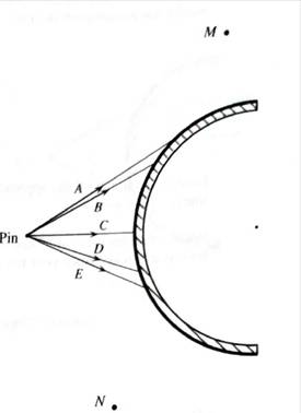
You have been provided with enlargement of this top view diagram.
1. Use a ruler and a protractor to draw the reflected rays on the enlargement. (Hint: The center of the cylindrical mirror is marked on the diagram.)
Describe how you determined the direction of each reflected ray.
2. For each of the reflected rays, use a dashed line to show the direction from which the reflected ray appears to have come.
Do all of the reflected rays appear to have come from the same point?
3. On the diagram. draw a ray. A between rays A and B. Draw the corresponding reflected ray.Which more nearly appear to pass through the same point: the reflected rays A, A’, and B or the reflected rays A, B, and C?
Determine and label the approximate location at which an observer at N would see an image of the pin.
Would the observers at M and N agree on the location of the image of the pin? Explain how you can tell from your ray diagram.
Would the observers at M and N agree on the location of the image of the pin? Explain how you can tell from your ray diagram.
4. Ask a tutorial instructor for a semi-cylindrical mirror. Place the mirror on the enlargement and use the method of parallax to check your predictions. (You may find it helpful to tape the mirror onto the diagram.) If there are any inconsistencies between your predictions and your observations, resolve the inconsistencies.
Want to see the full answer?
Check out a sample textbook solution
Chapter 10 Solutions
Tutorials in Introductory Physics
Additional Science Textbook Solutions
University Physics (14th Edition)
The Cosmic Perspective Fundamentals (2nd Edition)
Life in the Universe (4th Edition)
Conceptual Physical Science (6th Edition)
An Introduction to Thermal Physics
Physics (5th Edition)


- Construct ray diagrams to determine the location, orientation, size, and type of images formed by a curved mirror. Using the protractor and the ruler, copy each of the diagrams (A – F) below on a separate sheet of paper. As much as possible, use the four principal rays to locate the image formed in a curved mirror.arrow_forwardTwo plane mirrors are at an angle of ?1 = 53.6° with each other as in the side view shown in the figure below. If a horizontal ray is incident on mirror 1, at what angle ?2 does the outgoing reflected ray make with the surface of mirror 2? Answer in degrees °arrow_forwardTwo plane mirrors are at an angle of ?1 = 57.6° with each other as in the side view shown in the figure below. If a horizontal ray is incident on mirror 1, at what angle ?2 does the outgoing reflected ray make with the surface of mirror 2?arrow_forward
- A horizontal light ray initially in air (n1 = 1) approaches a prism as shown in the diagram below. The prism is in the shape of a right triangle and has an index of refraction of 1.5 (i.e. n2 = 1.5).a. Draw the trajectory of the light ray to show how it enters and exits theprism.arrow_forwardA converging (concave) mirror with a focal length of 7 cm is held 4 cm from your face. a. Determine the image location. Insert your solution here: b. What is the magnification of the image? Use the formula belowarrow_forwardTwo flat mirrors make an angle of 90.0° with each other, as diagrammed below. An incoming ray makes an angle of ? = 45° with the normal of mirror A. Use the law of reflection to determine the angle of reflection from mirror B. ° from the normal line of mirror B. What is unusual about the incoming light for this arrangement of mirrors? The ray reflected from the second mirror is never parallel to the incoming ray.The ray reflected from the second mirror is always parallel to the incoming ray. There is no reflected ray.arrow_forward
- If the radius of curvature of the mirror in diagram A is 15 cm and the object which is 10 cm long is placed 20 cm away from the mirror, then, find: a. the location of image b. size of image. Reminder: Always show your solution.arrow_forwardA concave lens refracts parallel rays in such a way that they are bent away from the axis of the lens. For this reason, a concave lens is referred to as a diverging lens. Part A: Consider the following diagrams, where F represents the focal point of a concave lens. In these diagrams, the image formed by the lens is obtained using the ray tracing technique. Which diagrams are accurate?(Figure 1) *Type A if you think that only diagram A is correct, type AB if you think that only diagrams A and B are correct, and so on. Part B: If the focal length of the concave lens is -7.50 cm , at what distance d_o from the lens should an object be placed so that its image is formed 3.70 cm from the lens?arrow_forwardFour ray diagrams are shown below. f1, f2 are the focal points for the lenses respectively as shown from left to right. when both focal points occur at the same point their position is designated as "f1/f2". Identify the TWO ray diagrams that show the correct position for the FINAL image for the two-lens systems shown below.arrow_forward
- Direction: Answer the following problems using mirror equation and magnification. Then describe the image formed for each number. (Type, Orientation and Magnification) 1. A 4.00-cm tall light bulb is placed a distance of 45.7 cm from a concave mirror having a focal length of 15.2 cm. Determine the image distance and the image height.arrow_forwardYou are imaging a pencil through a thin, converging lens as shown in the image below. If p (the distance from the object to the center of the thin lens) is 8.15m and the focal length of the thin lens is 0.42m, how far away (in meters) from the center of the thin lens is the real image located (the real image will be on the right-side of the lens in this particular example illustrated below)? Ray 1 Ray 1 focal point Ray 2 Sis Secondary Ray 3 Ray 3 Object Converging lens focal point Principal Real image Note: Do not explicitly include units in your answer (it is understood the unit is meter). Enter only a number. If you do enter a unit, your answer will be counted wrong.arrow_forwardYou will need a straightedge and a protractor for both problems on this homework. 1. Image Formation by a Cylindrical Mirror A pin is placed in front of a semi-cylindrical mirror as shown in the top-view diagram below. Location of observer 1 X Location of observer 2 Mirror Pin omor 16arrow_forward
 College PhysicsPhysicsISBN:9781305952300Author:Raymond A. Serway, Chris VuillePublisher:Cengage Learning
 University Physics (14th Edition)PhysicsISBN:9780133969290Author:Hugh D. Young, Roger A. FreedmanPublisher:PEARSON
 Introduction To Quantum MechanicsPhysicsISBN:9781107189638Author:Griffiths, David J., Schroeter, Darrell F.Publisher:Cambridge University Press
 Physics for Scientists and EngineersPhysicsISBN:9781337553278Author:Raymond A. Serway, John W. JewettPublisher:Cengage Learning
 Lecture- Tutorials for Introductory AstronomyPhysicsISBN:9780321820464Author:Edward E. Prather, Tim P. Slater, Jeff P. Adams, Gina BrissendenPublisher:Addison-Wesley
 College Physics: A Strategic Approach (4th Editio...PhysicsISBN:9780134609034Author:Randall D. Knight (Professor Emeritus), Brian Jones, Stuart FieldPublisher:PEARSON