
Concept explainers
Videos
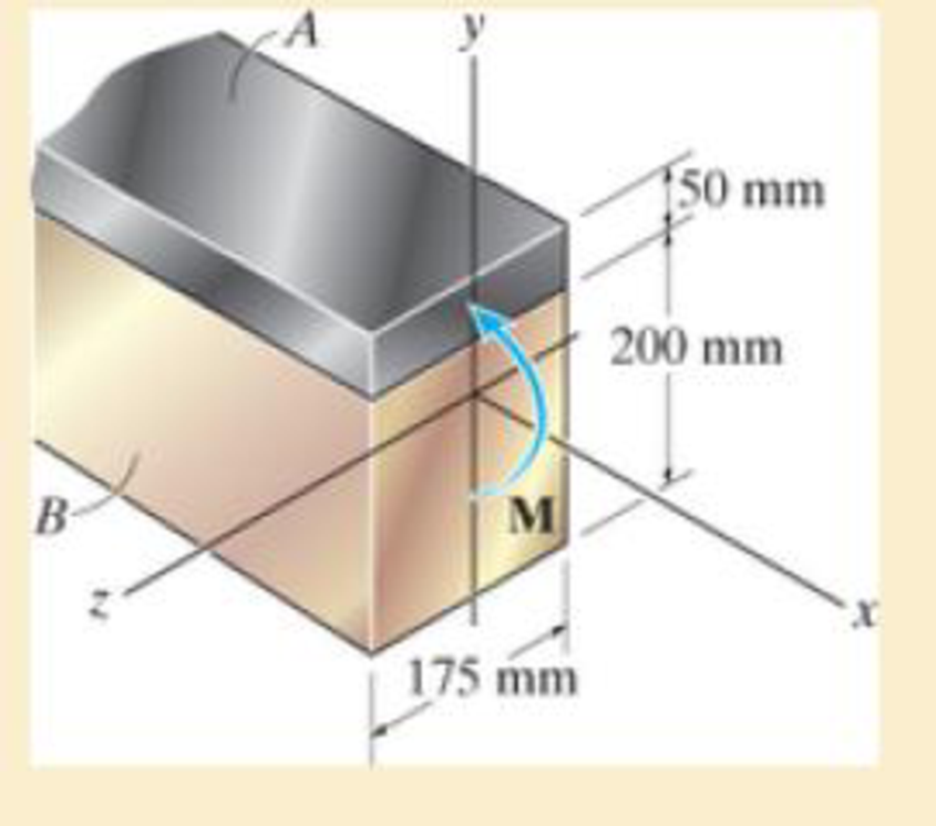
The composite beam is made of steel (A) bonded to brass (B) and has the cross section shown. If it is subjected to a moment of M = 6.5 kN · m, determine the maximum bending stress in the brass and steel. Also, what is the stress in each material at the seam where they are bonded together? Ebr = 100 GPa, Est = 200 GPa.
Prob. 6–120

Learn your wayIncludes step-by-step video

Chapter 6 Solutions
Mechanics of Materials
Additional Engineering Textbook Solutions
Automotive Technology: Principles, Diagnosis, And Service (6th Edition) (halderman Automotive Series)
Engineering Mechanics: Statics & Dynamics (14th Edition)
Thinking Like an Engineer: An Active Learning Approach (4th Edition)
INTERNATIONAL EDITION---Engineering Mechanics: Statics, 14th edition (SI unit)
Applied Fluid Mechanics (7th Edition)
Automotive Technology: Principles, Diagnosis, and Service (5th Edition)


- 6-126 The wooden section of the beam is reinforced with two steel plates as shown. II the beam is subjected to an Internal moment of M-30 EN - m,determine the maximum bending stresses developed in the steel and wood. Sketch the stress distribution over the cros section. Take E – 10 GPa and E-200 GPa. 15 mim 150 mm 15 mim 100 mim Probs. 6-125/126arrow_forwardThe allowable bending stress for the bar is sallow = 200 MPa. Determine the maximum moment M that can be applied to the bar.arrow_forward6-54. The beam is made from three boards nailed together as shown. If the moment acting on the cross section is M = 600 N - m, determine the maximum bending stress in the beam. Sketch a three-dimensional view of the stress distribution acting over the cross section. 25 mm 150 mm 20 mm 200 mm M - 600N-m 20 mmarrow_forward
- 6-125. The beam is made from three types of plastic that are identified and have the moduli of elasticity shown in the figure. Determine the maximum bending stress in the PVC. 500 lb 500 Ib PVC EPVC= 450 ksi Escon E = 160 ksi %3D Bakelite E = 800 ksi E-3 ft 4 ft 3 ft I in. 2 in. 2 in. 3 in.arrow_forwardThe beam has the rectangular cross section shown. If w = 1 kN>m, determine the maximum bending stress in the beam. Sketch the stress distribution acting over the cross section.arrow_forward"6-120. The composite beam is made of steel (A) bonded to brass (B) and has the cros section shown. IIt is subjected to a moment of M - 65 KN - m, determine the maximum bending stress in the brass and steel. Alsa, what is the stres In cach material at the seam where they are bonded together? E- 100 GPa, E-20O GPa. 6-12L The composile beam is made of steel (A) bonded to bras (8) and has the cros section shown. II he alkwable bending stress far the sted is (oae- 180 MPa, and for the bras (oa-0 MPa, delermine the matimum moment M that can be appiled to the beam. -100 GPa, E-200 GPa Imim Y 200 mm 175 m Probs. 6-12121arrow_forward
- If the beam in Prob. 6–28 has a rectangular cross section with a width b and a height h, determine the absolute maximum bending stress in the beam.arrow_forwardThe aluminum rod has a cross-shaped cross section. If subjected to the moment M = 8 kN x m, determine the bending stress acting at points A and B and show the results acting on volume elements located at these points. 100 mm 20 mm 100 mm B M = 8 kN-m 20 mm- 50 mm 50 mmarrow_forwardThe aluminum strut has a cross-sectional area in the form of a cross. It is subjected tothe Moment M = 8 KN.m. (i) Determine the bending stress acting at points A and B; (ii)Determine the maximum bending stress in the beam and sketch a three dimensional view of thestress distribution acting over the entire cross-sectional area.arrow_forward
- The bar has a thickness of 0.5 in. and is subjected to a moment of 600 lb # ft. Determine the maximum bending stress in the bar.arrow_forward5. If the radius of each notch on the pictured bending plate is r = 10 mm, determine the largest moment M that can be applied if the loading is of fatigue nature and the maximum allowable bending stress is 180 MPa. 20 mm 125 mm- 165 mm Marrow_forwardA member having the dimensions shown is used to resist an internal bending moment of M kNm. Determine the maximum stress in the member if the moment is applied (a) about the z axis (as shown) (b) about the y axis. Sketch the stress distribution for each case. Take: M= 90 kNm A mm A= 200 mm B= 150 mm B mm Solution: The moment of inertia of the cross-section about z and y axes are I;-4 1 - AB³ 12 (10) m* I BA = (10) m*arrow_forward
 Elements Of ElectromagneticsMechanical EngineeringISBN:9780190698614Author:Sadiku, Matthew N. O.Publisher:Oxford University Press
 Mechanics of Materials (10th Edition)Mechanical EngineeringISBN:9780134319650Author:Russell C. HibbelerPublisher:PEARSON
 Thermodynamics: An Engineering ApproachMechanical EngineeringISBN:9781259822674Author:Yunus A. Cengel Dr., Michael A. BolesPublisher:McGraw-Hill Education
 Control Systems EngineeringMechanical EngineeringISBN:9781118170519Author:Norman S. NisePublisher:WILEY
 Mechanics of Materials (MindTap Course List)Mechanical EngineeringISBN:9781337093347Author:Barry J. Goodno, James M. GerePublisher:Cengage Learning
 Engineering Mechanics: StaticsMechanical EngineeringISBN:9781118807330Author:James L. Meriam, L. G. Kraige, J. N. BoltonPublisher:WILEY