
Mechanics of Materials
11th Edition
ISBN: 9780137605460
Author: Russell C. Hibbeler
Publisher: Pearson Education (US)
expand_more
expand_more
format_list_bulleted
Concept explainers
Videos
Textbook Question
Chapter 4.2, Problem 1FP
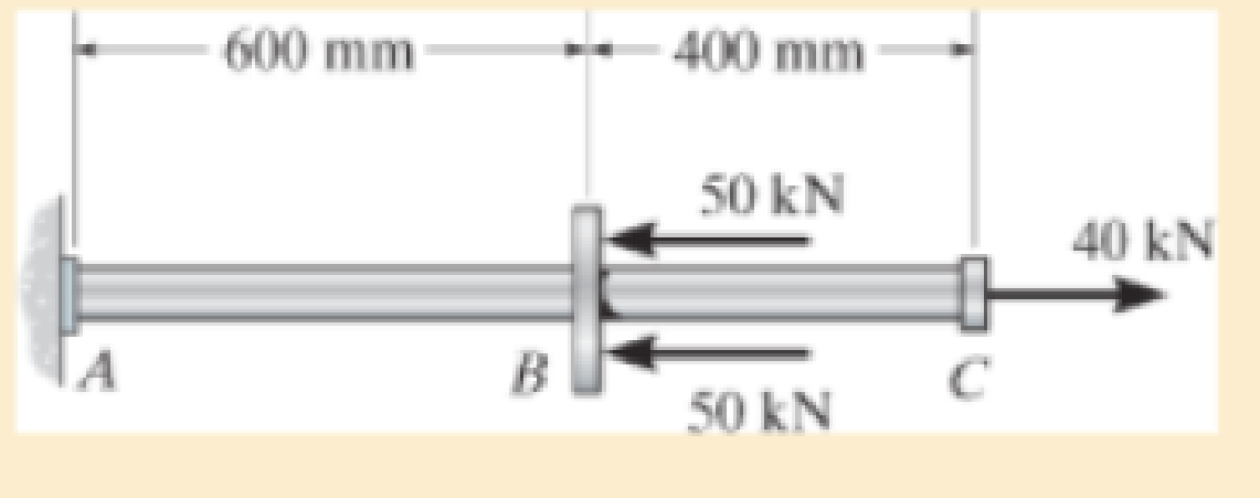
The 20-mm-diameter A-36 steel rod is subjected to the axial forces shown. Determine the displacement of end C with respect to the fixed support at A.
Expert Solution & Answer
Want to see the full answer?
Check out a sample textbook solution
Students have asked these similar questions
The 20 mm diameter steel shaft AB is attached into the rigid wall at B and supported by a smooth bearing at A. The lever AC is welded to the end of the shaft. If the downward force P will produce a 50 mm vertical displacement at the free end of lever AC, determine the force P if G = 83 GPa.
The 20-mm-diameter A-36 steel rod is subjected to the axial forces shown. Determine the displacement of end C with respect to the fixed support at A.
10. The 20-mm-diameter A-36 steel rod is subjected to the axial forces shown.
Determine the displacement of end C with respect to the fixed support at A.
600 mm
400 mm
50 kN
40 kN
B
50 kN
Chapter 4 Solutions
Mechanics of Materials
Ch. 4.2 - The 20-mm-diameter A-36 steel rod is subjected to...Ch. 4.2 - Segments AB and CD of the assembly are solid...Ch. 4.2 - The 30-mm-diameter A992 steel rod is subjected to...Ch. 4.2 - If the 20-mm-diameter rod is made of A-36 steel...Ch. 4.2 - The 20-mm-diameter 2014-T6 aluminum rod is...Ch. 4.2 - The 20-mm-diameter 2014-T6 aluminum rod is...Ch. 4.2 - The copper shaft is subjected to the axial loads...Ch. 4.2 - The A-36 steel rod is subjected to the loading...Ch. 4.2 - The A-36 steel rod is subjected to the loading...Ch. 4.2 - The A-36 steel drill shaft of an oil well extends...
Ch. 4.2 - Prob. 8PCh. 4.2 - The post is made of Douglas fir and has a diameter...Ch. 4.2 - The post is made of Douglas fir and has a diameter...Ch. 4.2 - The coupling rod is subjected to a force of 5 kip....Ch. 4.2 - The pipe is stuck in the ground so that when it is...Ch. 4.2 - The assembly consists of three titanium...Ch. 4.2 - The assembly consists of two rigid bars that are...Ch. 4.2 - The truss consists of three members, each made...Ch. 4.2 - Solve Prob. 426 when the load P acts vertically...Ch. 4.2 - The ball is truncated at its ends and is used to...Ch. 4.5 - The column is constructed from high-strength...Ch. 4.5 - The column is constructed from high-strength...Ch. 4.5 - The A-36 steel pipe has a 6061-T6 aluminum core....Ch. 4.5 - The 304 stainless steel post A has a diameter of...Ch. 4.5 - The 304 stainless steel post A is surrounded by a...Ch. 4.5 - The 10-mm-diameter steel bolt is surrounded by a...Ch. 4.5 - The rigid beam is supported by the three suspender...Ch. 4.5 - The bolt AB has a diameter of 20 mm and passes...Ch. 4.5 - If the gap between C and the rigid wall at D is...Ch. 4.5 - The support consists of a solid red brass C83400...Ch. 4.5 - Prob. 55PCh. 4.5 - The three A-36 steel wires each have a diameter of...Ch. 4.5 - The A-36 steel wires AB and AD each have a...Ch. 4.5 - The assembly consists of two posts AB and CD each...Ch. 4.5 - The assembly consists of two posts AB and CD each...Ch. 4.5 - The assembly consists of two posts AB and CD each...Ch. 4.5 - The wheel is subjected to a force of 18 kN from...Ch. 4.6 - The C83400-red-brass rod AB and 2014-T6- aluminum...Ch. 4.6 - The assembly has the diameters and material...Ch. 4.6 - Prob. 72PCh. 4.6 - Prob. 77PCh. 4.6 - Prob. 80PCh. 4.6 - The 50-mm-diameter cylinder is made from Am...Ch. 4.6 - The 50-mm-diameter cylinder is made from Am...Ch. 4.6 - The metal strap has a thickness t and width w and...Ch. 4.9 - Determine the maximum normal stress developed in...Ch. 4.9 - If the allowable normal stress for the bar is...Ch. 4.9 - Prob. 89PCh. 4.9 - The A-36 steel plate has a thickness of 12 mm. If...Ch. 4.9 - Determine the maximum axial force P that can be...Ch. 4.9 - Determine the maximum normal stress developed in...Ch. 4.9 - The member is to be made from a steel plate that...Ch. 4.9 - Prob. 96PCh. 4.9 - The bar has a cross-sectional area of 0.5 in2 and...Ch. 4.9 - The distributed loading is applied to the rigid...Ch. 4.9 - The distributed loading is applied to the rigid...Ch. 4.9 - The rigid lever arm is supported by two A-36 steel...Ch. 4.9 - The rigid lever arm is supported by two A-36 steel...Ch. 4.9 - The wire BC has a diameter of 0.125 in. and the...Ch. 4.9 - Prob. 104PCh. 4.9 - Prob. 106PCh. 4 - The assembly consists of two A992 steel bolts AB...Ch. 4 - The assembly shown consists of two A992 steel...Ch. 4 - The rods each have the same 25-mm diameter and...Ch. 4 - Two A992 steel pipes, each having a...Ch. 4 - The force P is applied to the bar, which is made...Ch. 4 - The 2014-T6 aluminum rod has a diameter of 0.5 in....Ch. 4 - The 2014-T6 aluminum rod has a diameter of 0.5 in....Ch. 4 - The rigid link is supported by a pin at A and two...Ch. 4 - The joint is made from three A992 steel plates...
Knowledge Booster


Learn more about
Need a deep-dive on the concept behind this application? Look no further. Learn more about this topic, mechanical-engineering and related others by exploring similar questions and additional content below.Similar questions
- If P = 4.1 kN , determine the horizontal displacement of end F of rod EF.arrow_forwardThe assembly consists of a 30mm diameter aluminum bar ABC with fixed collar at B and a 10mm diameter steel rod CD. Determine the displacement of point D when the assembly is loaded as shown. Neglect the size of the collar at B and the connection at C. Modules of elasticity for steel= 200GPA and for aluminum =70GPAarrow_forward3. The rigid bars AB and CD are supported by pins at A and D. The vertical rods are made of aluminum and bronze. Determine the vertical displacement of the point where the force P = 10 kips is applied. Neglect the weights of the members. Aluminum L= 4 f A=0.75 in. E= 10x 10 psi B 4 ft Bronze L= 5 A A=0.25 in.? E= 12x 10 psi 2 ft--2 ft-→arrow_forward
- The aluminum shaft, composed of three segments, is fastened to rigid supports at A and D. Calculate the maximum shear stress in each segment when the two torques are appliedarrow_forwardThe L-shaped frame is made from two segments, each of length L and flexural stiffness EI. If it is subjected to the uniform distributed load, determine the vertical displacement of point B.arrow_forwardThe L-shaped frame is made from two segments, each of length L and flexural stiffness EI. If it is subjected to the uniform distributed load, determine the horizontal displacement of point C.arrow_forward
- The steel bars AC and BC, each of cross-sectional area 120 mm2, are joined at C with a Determine the displacement of point C caused by the 15-kN load. Use E = 200 GPa for steel.arrow_forwardBoth portions of the rod ABC are made of an aluminum for which E = 70 GPa. What is the corresponding displacement at B in millimeter if P = 57 kN and Q = 397 kN?arrow_forwardThe compound shaft made from the same material consisting of two segments AC and CB is firmly attached to rigid supports. The allowable shear stress in the shaft is limited to 5500 psi. Determine the maximum torque TO that may be applied at C. Calculate also the angular rotation incurred by segment BC. Use G= 12 x 106 psi.arrow_forward
- The 20-mm-diameter 2014-T6 aluminum rod is subjected to the uniform distributed axial load. Determine the displacement of end A.arrow_forwardThe composite shaft, consisting of aluminum, copper, and steel sections, is subjected to the loading shown. Determine the displacement of B with respect to C. The cross-sectional area and modulus of elasticity for eachsection are shown in the figure. Neglect the size of the collars at B and C.arrow_forwardThe assembly consists of two 10-mm diameter red brass C83400 copper rods AB and CD, a 15-mm diameter 304 stainless steel rod EF, and a rigid bar G. If the horizontal displacement of end F of rod EF is 0.45 mm, determine thethe magnitude of P.arrow_forward
arrow_back_ios
SEE MORE QUESTIONS
arrow_forward_ios
Recommended textbooks for you
 Elements Of ElectromagneticsMechanical EngineeringISBN:9780190698614Author:Sadiku, Matthew N. O.Publisher:Oxford University Press
 Mechanics of Materials (10th Edition)Mechanical EngineeringISBN:9780134319650Author:Russell C. HibbelerPublisher:PEARSON
 Thermodynamics: An Engineering ApproachMechanical EngineeringISBN:9781259822674Author:Yunus A. Cengel Dr., Michael A. BolesPublisher:McGraw-Hill Education
 Control Systems EngineeringMechanical EngineeringISBN:9781118170519Author:Norman S. NisePublisher:WILEY
 Mechanics of Materials (MindTap Course List)Mechanical EngineeringISBN:9781337093347Author:Barry J. Goodno, James M. GerePublisher:Cengage Learning
 Engineering Mechanics: StaticsMechanical EngineeringISBN:9781118807330Author:James L. Meriam, L. G. Kraige, J. N. BoltonPublisher:WILEY
Elements Of Electromagnetics
Mechanical Engineering
ISBN:9780190698614
Author:Sadiku, Matthew N. O.
Publisher:Oxford University Press
Mechanics of Materials (10th Edition)
Mechanical Engineering
ISBN:9780134319650
Author:Russell C. Hibbeler
Publisher:PEARSON
Thermodynamics: An Engineering Approach
Mechanical Engineering
ISBN:9781259822674
Author:Yunus A. Cengel Dr., Michael A. Boles
Publisher:McGraw-Hill Education
Control Systems Engineering
Mechanical Engineering
ISBN:9781118170519
Author:Norman S. Nise
Publisher:WILEY
Mechanics of Materials (MindTap Course List)
Mechanical Engineering
ISBN:9781337093347
Author:Barry J. Goodno, James M. Gere
Publisher:Cengage Learning
Engineering Mechanics: Statics
Mechanical Engineering
ISBN:9781118807330
Author:James L. Meriam, L. G. Kraige, J. N. Bolton
Publisher:WILEY
EVERYTHING on Axial Loading Normal Stress in 10 MINUTES - Mechanics of Materials; Author: Less Boring Lectures;https://www.youtube.com/watch?v=jQ-fNqZWrNg;License: Standard YouTube License, CC-BY