
Videos
For the battery of bulbs (purely resistive) appearing in Fig. 20.48 :
a. Determine the total power dissipation.
b. Calculate the total reactive and apparent power.
c. Find the source current Is.
d. Calculate the resistance of each bulb for the specified operating conditions.
e. Determine the currents I1 and I2.
(a)
The total power dissipation.
Answer to Problem 1P
The total power dissipated is
Explanation of Solution
Calculation:
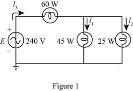
The given circuit diagram is shown in Figure 1.
The power dissipated in bulb 1 is
The total power dissipation is given by the sum of power dissipated in individual bulbs, that is,
Here,
Substitute
Conclusion:
Therefore, the total power dissipated is
(b)
The total reactive and apparent power.
Answer to Problem 1P
The reactive power dissipated in the bulbs is
Explanation of Solution
Calculation:
As the bulbs are purely resistive in nature therefore, the reactive power dissipated in bulb is zero that is,
The apparent power is given by,
Substitute
Conclusion:
Therefore, the reactive power dissipated in bulb is
(c)
The source current
Answer to Problem 1P
The source current
Explanation of Solution
Calculation:
The source voltage
The apparent power is given by,
Substitute
Conclusion:
Therefore, the source current
(d)
The resistance of each bulb.
Answer to Problem 1P
The resistance of bulb 1 is
Explanation of Solution
Calculation:
The power dissipated in first bulb is given by,
Substitute
The voltage
Substitute
From the figure 1 it can be seen that voltage
Substitute
The power dissipated in bulb 2 is given by,
Substitute
The power dissipated in bulb 3 is given by,
Substitute
Conclusion:
Therefore, the resistance of bulb 1 is
(e)
The current
Answer to Problem 1P
The current
Explanation of Solution
Calculation:
The value of current
Substitute
The current
Substitute
Conclusion:
Therefore, the current
Want to see more full solutions like this?
Chapter 20 Solutions
Introductory Circuit Analysis (13th Edition)
Additional Engineering Textbook Solutions
Fundamentals of Electric Circuits
Microelectronics: Circuit Analysis and Design
ELECTRICITY FOR TRADES (LOOSELEAF)
Programmable Logic Controllers
ANALYSIS+DESIGN OF LINEAR CIRCUITS(LL)
Electronics Fundamentals: Circuits, Devices & Applications


- For controlled half wave rectifier, R=44ohm, f=50Hz and Vm=280V and x=0,9 rad. Calculate the power (W) absorbed by the load. In your calculations, take 3 digits after the comma and take pi = 3,14; Enter your answer into the system in terms of the desired unit only as a number.arrow_forwardI need help with (d) . Thanks 1. Consider a half-wave rectifier circuit with a resistive load of 25 Ωand a 60 Hz ac source of 110V rms.(a) Determine v0(t) and i0(t)(b) Calculate the rms values of v0(t) and i0(t)(c) Calculate the average power delivered to the load(d) Repeat questions a , b, and c to the full wave rectifier of Figure below with R-load and thesame source and load parametersarrow_forwardist out all the major components in a thermal power plantarrow_forward
- Lumean Area Method 1. A room 100 ft x 300 ft requires 80 foot-candle. It is to be illuminated byduplex fluorescent lamp. The 2-T20 watt lamp has an output of 3200lumens, maintenance factor is 0.7 and coefficient of utilization is 0.6.Calculate the number of luminaires. 2. A room 20 m by 10 m is to be illuminated by 10 lamps at an averageillumination of 50 lux. If CU = 0.50 and MF = 0.83, the mean sphericalcandlepower of each lamp is nearest to…arrow_forwardFor controlled half wave rectifier, R=44ohm, f=50Hz and Vm=280V and x=0,9 rad. Calculate the average load voltage (V). In your calculations, take 3 digits after the comma and take = 3,14; Enter your answer into the system in terms of the desired unit only as a number.arrow_forwardPlease write solution clearly.arrow_forward
- q25/a Write the features of Air circuit breaker and mention its application.arrow_forwardİNGİLİZCE TÜRKÇE RUSÇA Measuring the Hall coefficient allows to determine which of the following? a) temperature coefficient and thermal conductivity b) none of the above c) mobility of load carriers d) type of conductivity and concentration of charge carriers Bu bilgi faydalı mıydı? Evet Hayliarrow_forwardA E-E-E AaBbCcl AaBbC AaBbCcl Emphasis Heading 1 Heading 6 Paragraph Styles Q4. What are the types of Power supply available in the Laboratory? Q5. How many setup for power supplies are available in the lab? Page 4 of 5 (United States)arrow_forward
- 20.a. Which of the following lead-acid battery voltages has the highest value?A. Equalize voltageB. Discharge voltageC. Floating voltageD. Open-circuit voltagels 20.b. Leady oxide is a material that?s usually composed ofA. 25% free lead and 75% lead oxide.B. 50% free lead and 50% lead oxide.C. 10% free lead and 90% lead oxide.D. 60% free lead and 40% lead oxide.arrow_forward1. A 6 ampere supply has a frequency of 25 Hz. Find the instantaneous value of current a. at 0.00530 sec from zero going to the positive direction. b. at 0.00530 sec from zero going to the negative direction. c. at 530 degrees.arrow_forwardDiscussion : 1- Discuss the suitable method of thermocouple calibration and show the wrongs in this experiment . 2- Sketch the curve between the thermocouple reading and thermometer reading and what we can get from the curve (find the relation between the T&V). 3- By what we can correct the readings of the thermocouple ? 4- Write a short answer a bout the method used in junction welding of thermocouple junction . Use the following reading Table of Type E Thermocouple (chromel-constantan) temperature (°C) Thermoelectric Voltage in Millivolts 0.000 10 0.591 20 1.192 30 1.801 40 2.420 50 3.048 60 3.685 70 4.330 80 4.985 5.648 6.319 90 100 110 6.998 120 7.685 130 8.379 9.081 9.789 140 150arrow_forward
 Introductory Circuit Analysis (13th Edition)Electrical EngineeringISBN:9780133923605Author:Robert L. BoylestadPublisher:PEARSON
 Delmar's Standard Textbook Of ElectricityElectrical EngineeringISBN:9781337900348Author:Stephen L. HermanPublisher:Cengage Learning
 Programmable Logic ControllersElectrical EngineeringISBN:9780073373843Author:Frank D. PetruzellaPublisher:McGraw-Hill Education
 Fundamentals of Electric CircuitsElectrical EngineeringISBN:9780078028229Author:Charles K Alexander, Matthew SadikuPublisher:McGraw-Hill Education
 Electric Circuits. (11th Edition)Electrical EngineeringISBN:9780134746968Author:James W. Nilsson, Susan RiedelPublisher:PEARSON
 Engineering ElectromagneticsElectrical EngineeringISBN:9780078028151Author:Hayt, William H. (william Hart), Jr, BUCK, John A.Publisher:Mcgraw-hill Education,