
Fundamentals of Electric Circuits
6th Edition
ISBN: 9780078028229
Author: Charles K Alexander, Matthew Sadiku
Publisher: McGraw-Hill Education
expand_more
expand_more
format_list_bulleted
Videos
Textbook Question
Chapter 16.3, Problem 4PP
For the circuit shown in Fig. 16.12 with the same initial conditions, find the current through the inductor for all time t > 0.
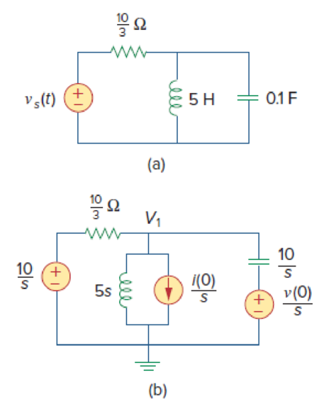
Figure 16.12
Expert Solution & Answer
Want to see the full answer?
Check out a sample textbook solution
Students have asked these similar questions
This allows
E ELECTRICAL
mple 3.8:
Consider the circuit in Fig. 16.12(a). Find the
value of the voltage
across the capacitor assuming that the value of vs(t) = 10u(t) V and
assume that at t = 0, -1 A flows through the inductor and +5 V is
across the capacitor.
19 2
EPARTM
%s (1)
ww
rell
(a)
5 H
0.1 F
INEERING
in with th
please show the clear equation
doos goo
lorms/d/e/1FAlpQLSeis9wjiqvOVB12Eo71MGSVR7NxRXIP
Join a Meeting- ..
movies.awesomese.. O d ll O ag
Question
The general solution of the following differential equation
y(5) – y' = 4x
is:
y(x) = ce + cze2* + cg cos(2x)
y(x) = +cze" + Cge*+ Cq cos(x)
+q, sin(2x) - 2x
+cg sin(x) – 2x?
This option
This option
y(x) - ce + czeco s(V3x)
y(x) = ce + cye 2* + cg cos(2x)
ta sin(2x) + Ax + B
+ege "si n(v3x) + Ax + B
This option
This option
Chapter 16 Solutions
Fundamentals of Electric Circuits
Ch. 16.2 - Determine vo(t) in the circuit of Fig. 16.6,...Ch. 16.2 - Prob. 2PPCh. 16.2 - Prob. 3PPCh. 16.3 - For the circuit shown in Fig. 16.12 with the same...Ch. 16.3 - Prob. 5PPCh. 16.3 - The initial energy in the circuit of Fig. 16.17 is...Ch. 16.4 - Prob. 7PPCh. 16.4 - Prob. 8PPCh. 16.4 - Prob. 9PPCh. 16.5 - Obtain the state variable model for the circuit...
Ch. 16.5 - Prob. 11PPCh. 16.5 - Prob. 12PPCh. 16.6 - For what value of is the circuit in Fig. 16.29...Ch. 16.6 - Prob. 14PPCh. 16.6 - Prob. 15PPCh. 16.6 - Synthesize the function Vo(s)Vin=2ss2+6s+10 using...Ch. 16 - Prob. 1RQCh. 16 - The current through an RL series circuit with...Ch. 16 - Prob. 3RQCh. 16 - Prob. 4RQCh. 16 - Prob. 5RQCh. 16 - Prob. 6RQCh. 16 - Prob. 7RQCh. 16 - Prob. 8RQCh. 16 - Prob. 9RQCh. 16 - Prob. 10RQCh. 16 - The current in an RLC circuit is described by...Ch. 16 - The differential equation that describes the...Ch. 16 - Prob. 3PCh. 16 - If R = 20 , L = 0.6 H, what value of C will make...Ch. 16 - The responses of a series RLC circuit are vc(t) =...Ch. 16 - Prob. 6PCh. 16 - Prob. 7PCh. 16 - Prob. 8PCh. 16 - Prob. 9PCh. 16 - The step responses of a series RLC circuit are Vc...Ch. 16 - The step response of a parallel RLC circuit is v =...Ch. 16 - Prob. 12PCh. 16 - Prob. 13PCh. 16 - Prob. 14PCh. 16 - For the circuit in Fig. 16.38. calculate the value...Ch. 16 - The capacitor in the circuit of Fig. 16.39 is...Ch. 16 - If is(t) = 7.5e2t u(t) A in the circuit shown in...Ch. 16 - Find v(t), t 0 in the circuit of Fig. 16.41. Let...Ch. 16 - The switch in Fig. 16.42 moves from position A to...Ch. 16 - Find i(t) for t 0 in the circuit of Fig. 16.43.Ch. 16 - In the circuit of Fig. 16.44, the switch moves...Ch. 16 - Find the voltage across the capacitor as a...Ch. 16 - Obtain v (t) for t 0 in the circuit of Fig....Ch. 16 - The switch in the circuit of Fig. 16.47 has been...Ch. 16 - Calculate v(t) for t 0 in the circuit of Fig....Ch. 16 - Prob. 26PCh. 16 - Find v (t) for t 0 in the circuit in Fig. 16.50.Ch. 16 - For the circuit in Fig. 16.51, find v(t) for t 0.Ch. 16 - Prob. 29PCh. 16 - Find vo(t), for all t 0, in the circuit of Fig....Ch. 16 - Prob. 31PCh. 16 - For the network in Fig. 16.55, solve for i(t) for...Ch. 16 - Using Fig. 16.56, design a problem to help other...Ch. 16 - Prob. 34PCh. 16 - Prob. 35PCh. 16 - Prob. 36PCh. 16 - Prob. 37PCh. 16 - The switch in the circuit of Fig. 16.61 is moved...Ch. 16 - Prob. 39PCh. 16 - Prob. 40PCh. 16 - Prob. 41PCh. 16 - Prob. 42PCh. 16 - Prob. 43PCh. 16 - Prob. 44PCh. 16 - Find v(t) for t 0 in the circuit in Fig. 16.68.Ch. 16 - Prob. 46PCh. 16 - Determine io(t) in the network shown in Fig....Ch. 16 - Prob. 48PCh. 16 - Find i0(t) for t 0 in the circuit in Fig. 16.72....Ch. 16 - Prob. 50PCh. 16 - In the circuit of Fig. 16.74, find i(t) for t 0.Ch. 16 - Prob. 52PCh. 16 - In the circuit of Fig. 16.76, the switch has been...Ch. 16 - Prob. 54PCh. 16 - Prob. 55PCh. 16 - Calculate io(t) for t 0 in the network of Fig....Ch. 16 - Prob. 57PCh. 16 - Prob. 58PCh. 16 - Find vo(t) in the circuit of Fig. 16.82 if vx(0) =...Ch. 16 - Prob. 60PCh. 16 - Prob. 61PCh. 16 - Using Fig. 16.85, design a problem to help other...Ch. 16 - Consider the parallel RLC circuit of Fig. 16.86....Ch. 16 - The switch in Fig. 16.87 moves from position 1 to...Ch. 16 - For the RLC circuit shown in Fig. 16.88, find the...Ch. 16 - For the op amp circuit in Fig. 16.89, find v0(t)...Ch. 16 - Given the op amp circuit in Fig. 16.90, if v1(0+)...Ch. 16 - Prob. 68PCh. 16 - Prob. 69PCh. 16 - Using Fig. 16.93, design a problem to help other...Ch. 16 - Prob. 71PCh. 16 - The transfer function of a system is H(s)=s23s+1...Ch. 16 - Prob. 73PCh. 16 - Design a problem to help other students better...Ch. 16 - Prob. 75PCh. 16 - For the circuit in Fig. 16.95, find H(s) =...Ch. 16 - Obtain the transfer function H(s) = VoVs for the...Ch. 16 - Prob. 78PCh. 16 - For the circuit in Fig. 16.97, find: (a) I1/Vs (b)...Ch. 16 - Refer to the network in Fig. 16.98. Find the...Ch. 16 - Prob. 81PCh. 16 - Prob. 82PCh. 16 - Refer to the RL circuit in Fig. 16.101. Find: (a)...Ch. 16 - A parallel RL circuit has R = 4 and L = 1 H. The...Ch. 16 - Prob. 85PCh. 16 - Prob. 86PCh. 16 - Prob. 87PCh. 16 - Prob. 88PCh. 16 - Develop the state equations for the circuit shown...Ch. 16 - Prob. 90PCh. 16 - Prob. 91PCh. 16 - Prob. 92PCh. 16 - Prob. 93PCh. 16 - Prob. 94PCh. 16 - Prob. 95PCh. 16 - Prob. 96PCh. 16 - A system is formed by cascading two systems as...Ch. 16 - Determine whether the op amp circuit in Fig....Ch. 16 - It is desired realize the transfer function...Ch. 16 - Prob. 100PCh. 16 - Prob. 101PCh. 16 - Synthesize the transfer function...Ch. 16 - Prob. 103CPCh. 16 - Prob. 104CPCh. 16 - Prob. 105CP
Knowledge Booster


Learn more about
Need a deep-dive on the concept behind this application? Look no further. Learn more about this topic, electrical-engineering and related others by exploring similar questions and additional content below.Similar questions
- The A matrix of a state space model has eigenvalues: [0.45 2.1j, -3.1] What conclusion can be drawn about the system stability and oscillations? O unstable and oscillates O stable and does not oscillate O stable and oscillates O unstable and does not oscillatearrow_forwardAlgorithmsStudent Transportation Expenses NU has very diverse students from different places. To reach the campus, each student must go through a sequence of stations to get to campus. Assume within the ith station you can pay x; to either get to station (i + 1) or (i + 2). At CSCI-304, we want to help our colleagues minimize their expenses to campus—it would be great especially after COVID-19.Input: expenses : array listing expenses to be paid at each station to move its values are non-negatives, and it has at least 2 valuesOutput: m: the expenses of transportation to the campus Note the campus station is execludedExample: Assume the below table contains the expenses per each station Station Cost 1 2 3 4 5 6 3 6.5 2 2 8 **In Python notebook**arrow_forwardDesign of 2nd-order LPF The poles of a normalized second-order LPF ([H(w = 0)| = 1) is shown on the complex plane below: %3Darrow_forward
- Given the ff. 2nd-order diff. equation, find the forced response and the natural responsearrow_forwardBelow is a linear mechanical system and free body diagrams related to this system. X2 (s) / F (s) transfer function 可 t-x1(t) 2 N/m M2 2 kg 5 M1 1 kg At) M2 2. 2- 1N-s/m 4. M1 3 3 sürtünmesiz'arrow_forward"signals_and systems_2nd_editic x solutions of chapter 2.pdf PDF Create collections and export to X+ File C:/Users/user/Downloads/Telegram%20ODesktop/lbi/signals_and_systems_2nd_edition_schaums_outline_series_hwei_... @ to e 2.64. Consider a discrete-time system whose input x[n] and output y[n] are related by y[n]-y[n-1]= x[n] y[n– 1]= x[n] with y[-1] = 0. Find the output y[n] for the following inputs: (a) x[n]= u[n]; (b) x[n]= u[n] Activate Windows Go to Settings to activate Windows 2.11 PM 0耳 へn#命意急 NG 4/7/2021 Type here to search -arrow_forward
- 3. Write the differential equations of the translational system. Then find the modeling in the space of states of the following mechanical system. Finally, pass from modeling in The space of states to a transfer function that describes the system.arrow_forwardConsider the following circuit which has single input X and single output Y. This circuit represents: CLK Y Mealy Model Moore Model Both Mealy and Moore Nonearrow_forwardSolve for VSS, Rx, Ryarrow_forward
- o(t) = [ce-at cosßt - e-atsinft (cosßt + sinßt) B-Assume that 2e-sinßt + becos est (cosßt-singt) "C Find a, b, c, B, and a such that (t) is a state-transition matrix and Isl-A=5³+5+ hown in Fig.6, in which the PID controller is usedarrow_forwardConsider the linear system described by its state space model: X1 = -3x1 + 2x2 + u *2 = -3x1 – x2 + u y = 2x1 + x2 + u Obtain the state diagram of the system. Compute the state transition matrix.arrow_forwardI Homework 6b 03182022.docx.pdf - Adobe Reader File Edit View Window Help 2 / 4 Tools Fill & Sign Comment Оpen 125% IT Sign In • Export PDF • Create PDF EP: RRE (Generalijed) Liiear Phase Filieus Euan Mart hin) - hcH-n) Gpes I I hin) --h(M.n) Types I&Z 2. Meven; (Ma6) M + maltipliro M adders X(n) Mesen be M odd ; (M=5) MA multijpleis M adders Madld Modd + For an ideal silicon p-n abrupt junction with NA = 5 x1016 cm and Np = See also cascade raalizationo in b.5.2 of OxS. 2021-10-20 19:02:14 -3 ст 5 x 10'5/cm³, 3 • Send Files • Store Files Calculate Vbi at 300K and 600K. Find the depletion layer width and maximum field at zero bias at T=300K. Hints: For Vbi calculation at T=600K, use Eg versus T formula (HW 1). 600 kT (600K)= kT(300K)x 300 3/2 600 N(600K)=N (300K)× 300 3/2 600 N, (600K)=N, (300K)× 300 3:36 AM Type here to search 日 27°C W 24-Mar-22arrow_forward
arrow_back_ios
SEE MORE QUESTIONS
arrow_forward_ios
Recommended textbooks for you
 Introductory Circuit Analysis (13th Edition)Electrical EngineeringISBN:9780133923605Author:Robert L. BoylestadPublisher:PEARSON
 Delmar's Standard Textbook Of ElectricityElectrical EngineeringISBN:9781337900348Author:Stephen L. HermanPublisher:Cengage Learning
 Programmable Logic ControllersElectrical EngineeringISBN:9780073373843Author:Frank D. PetruzellaPublisher:McGraw-Hill Education
 Fundamentals of Electric CircuitsElectrical EngineeringISBN:9780078028229Author:Charles K Alexander, Matthew SadikuPublisher:McGraw-Hill Education
 Electric Circuits. (11th Edition)Electrical EngineeringISBN:9780134746968Author:James W. Nilsson, Susan RiedelPublisher:PEARSON
 Engineering ElectromagneticsElectrical EngineeringISBN:9780078028151Author:Hayt, William H. (william Hart), Jr, BUCK, John A.Publisher:Mcgraw-hill Education,
Introductory Circuit Analysis (13th Edition)
Electrical Engineering
ISBN:9780133923605
Author:Robert L. Boylestad
Publisher:PEARSON
Delmar's Standard Textbook Of Electricity
Electrical Engineering
ISBN:9781337900348
Author:Stephen L. Herman
Publisher:Cengage Learning
Programmable Logic Controllers
Electrical Engineering
ISBN:9780073373843
Author:Frank D. Petruzella
Publisher:McGraw-Hill Education
Fundamentals of Electric Circuits
Electrical Engineering
ISBN:9780078028229
Author:Charles K Alexander, Matthew Sadiku
Publisher:McGraw-Hill Education
Electric Circuits. (11th Edition)
Electrical Engineering
ISBN:9780134746968
Author:James W. Nilsson, Susan Riedel
Publisher:PEARSON
Engineering Electromagnetics
Electrical Engineering
ISBN:9780078028151
Author:Hayt, William H. (william Hart), Jr, BUCK, John A.
Publisher:Mcgraw-hill Education,
Routh Hurwitz Stability Criterion Basic Worked Example; Author: The Complete Guide to Everything;https://www.youtube.com/watch?v=CzzsR5FT-8U;License: Standard Youtube License