
Videos
(a) The open-loop gain of an amplifier is
(a)
- The feedback transfer function for a given closed-loop gain and open-loop gain
- The ratio of closed loop gain to
Answer to Problem 12.1EP
(i) The feedback transfer function is
(ii) The ratio of closed loop gain to
Explanation of Solution
Given Information:
The open-loop gain of a feedback amplifier is
Calculation:
(i) Consider the general feedback amplifier representation in Figure 1. Here, a feedback section with feedback transfer function
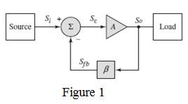
Substituting the open-loop gain and the closed-loop gain , the feedback transfer function can be obtained as,
(ii) Substituting the value of
(b)
(i) The feedback transfer function for a given closed-loop gain and open-loop gain
(ii) The ratio of closed loop gain to
Answer to Problem 12.1EP
(i) The feedback transfer function is
(ii) The ratio of closed loop gain to
Explanation of Solution
Given Information:
The open-loop gain of a feedback amplifier is
Calculation:
(i) Consider the general feedback amplifier representation in Figure 1. Here, a feedback section with feedback transfer function
Substituting the open-loop gain and the closed-loop gain , the feedback transfer function can be obtained as,
(ii) Substituting the value of
Want to see more full solutions like this?
Chapter 12 Solutions
Microelectronics: Circuit Analysis and Design


- What are the advantages of positive feedback amplifier?arrow_forwardWhat is a typical value of open-loop, low-frequency gain of an op-arop circuit? How does this compare to the ideal value?arrow_forward1. Calculate the gain of a negative-feedback amplifier having A = -2000 and B = -1/10. 2. If the gain of an amplifier changes from a value of – 1000 by 10%, calculate the gain change if the amplifier is used in a feedback circuit having B = – 1/20.arrow_forward
- Why negative feedback is applied in high gain amplifiers? Discuss the principles of negative voltage feedback in amplifiers with a neat diagram.arrow_forwardDesign a circuit consisting of three stages, with the output of the first stage being a square wave, the second stage being a triangular wave and the third stage being again a square wave of period 220us and 50% duty cycle. Increase value of the resistor in the -ve feedback path of the first stage by 2X and show how it affects the output waveform. (Note: use a relaxation oscillator).arrow_forward2. For the Feedback Amplifier circuit shown in Figure 4, determine the following: a. Identify the type of sampling and mixing for the amplifier. b. Calculate the feedback factor for the amplifier. c. Draw the small signal equivalent circuit for the amplifier with no feedback and calculate the voltage gain without any feedback. d. Calculate the voltage gain with feedback. e. Calculate input and output resistances of the amplifier with feedback. B=100; 2=2.5k12. No DC Calculations necessary. +15V IK: Vs look TON't 27k fig. lONf -15V 4. €2.5k ZONE lk $250 Yout F₂0 =20NF lokarrow_forward
- a) Obtain the open-loop transfer function. Go to page: 12 he closed-loop transfer function.. c) Find the value of gain and closed-loop poles at the imaginary axis crossing:... d) Write the range of k for which the closed system is stable.......….. e) Write the value of k that makes the system marginally stable:... f) What would be the period of oscillation. g) Find %OS, Tp, Ts, atk = 15. h) Find the steady-state errors when the input is r(t)= 0.62 u(t) step at k=15:.. H(s)G(s): k (s + 7)(s +1-j)(s +1+j)arrow_forwardThe circuit of Figure below uses current- (or shunt-) feedback bias. The Si transistor has ICEO = 0, B = 100, Rc= 2k2, Vcc = 12 V. Assume that; (VCEQ = Vcc /2). A. Find the value of Ibq B. Find the value of Rf C. Find the value of Rearrow_forwardCalculate the feedback gain AF value. RİF=? ROF=?arrow_forward
- Discuss the difference between the current series negative feedback amplifier and voltage shunt feedback amplifier in terms of output impedance, input impedance, voltage gain, bandwidth, distortion and noise.arrow_forwardQ1/ (a) A negative-feedback amplifier has a closed-loop gain of Af=100 and an open-loop gain of A =5 x 10*. Determine the feedback transfer function p. (b) If p=10.012 and Af = 80, determine the open-loop gain A.arrow_forwardWhat are the three canonic amplifier circuit types with the negative feedback?arrow_forward
 Introductory Circuit Analysis (13th Edition)Electrical EngineeringISBN:9780133923605Author:Robert L. BoylestadPublisher:PEARSON
 Delmar's Standard Textbook Of ElectricityElectrical EngineeringISBN:9781337900348Author:Stephen L. HermanPublisher:Cengage Learning
 Programmable Logic ControllersElectrical EngineeringISBN:9780073373843Author:Frank D. PetruzellaPublisher:McGraw-Hill Education
 Fundamentals of Electric CircuitsElectrical EngineeringISBN:9780078028229Author:Charles K Alexander, Matthew SadikuPublisher:McGraw-Hill Education
 Electric Circuits. (11th Edition)Electrical EngineeringISBN:9780134746968Author:James W. Nilsson, Susan RiedelPublisher:PEARSON
 Engineering ElectromagneticsElectrical EngineeringISBN:9780078028151Author:Hayt, William H. (william Hart), Jr, BUCK, John A.Publisher:Mcgraw-hill Education,